Connectivity in a network dataset is based on geometric coincidences of line endpoints, line vertices, and points. It also depends on the connectivity rules that you set as properties on the network dataset.
Group connectivity
Connectivity in the ArcGIS Network Analyst extension begins with the definition of connectivity groups. Each edge source is assigned to exactly one connectivity group, and each junction source can be assigned to one or more connectivity groups. A connectivity group can contain any number of sources. How network elements connect depends on the connectivity groups that the elements are in. For example, two edges created from two distinct source feature classes can connect if they are in the same connectivity group. If they are in separate connectivity groups, the edges won't connect unless they are joined by a junction that participates in both connectivity groups.
Connectivity groups are used to model multimodal transportation systems. For each connectivity group, you select the network sources that interconnect. In the subway and street multimodal network example below, metro lines and metro entrances are all assigned to the same connectivity group. Note that Metro_Entrance is also in the connectivity group with streets. It forms the link between the two connectivity groups. Any path between the groups must travel through a shared metro entrance. For example, a route solver may determine that a pedestrian's best route between two locations in a city is to walk on the street to a metro entrance, board a subway train, take another train at a line-crossing station, and exit through another metro entrance. Connectivity groups keep the two networks distinct, yet connect them at shared junctions (metro entrances).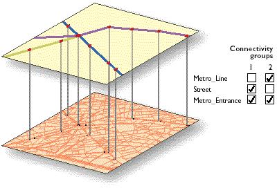
Connect edges in a connectivity group
Edges in the same connectivity group can connect in two ways—endpoint or vertex—set by the connectivity policy on the edge source.
- If you set endpoint connectivity, line features become edges joining only at coincident endpoints.

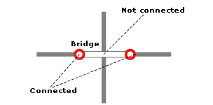
In this case, line feature l1 becomes edge element e1, and line feature l2 becomes edge element e2. There will always be one edge element created for one line feature with this connectivity policy. Building networks with endpoint connectivity is one way to model crossing objects, such as bridges. To model this case, the two sources, bridges and streets, are placed in the same connectivity group (1). The streets source is assigned any vertex connectivity to allow street features to connect to other street features at coincident vertices. The bridges source is assigned endpoint connectivity. This means bridges connect to other edge features only at their endpoints. Consequently, any street going under the bridge will not be connected to the bridge. The bridge will connect to other streets at its endpoints.
If you have only one source in your network that you want to use to model overpasses (bridges) and underpasses (tunnels), you could use elevation fields on planar data. For more information, see the Elevation fields section below.
Note:
If you are working with multipart line features, understand that Network Analyst treats the vertices at the ends of each part as endpoints, not vertices.
- If you set any vertex connectivity, line features are split into multiple edges at coincident vertices. Setting this policy is important if your street data is structured such that streets meet other streets at vertices.
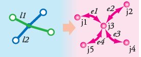
In this case, two polylines crossing at a shared vertex position are split into four edges, with a junction at the vertex. Edges e1 and e3 are identified with the source feature class and object ID of line feature l1. Edges e2 and e4 are identified with the source feature class and object ID of line feature l2. Junction j3 will be a newly created system junction. Junctions j1, j2, j4, and j5 will either be system junctions or junctions from coincident points from a source feature class.
Caution:
Not all crossing line features can produce connected edges. If they do not share any coincident endpoints or vertices, no connectivity policy will create a junction at the point of intersection. Street data for network datasets must be cleaned first so that either vertices or endpoints are present at all intended junctions.

If you need to remedy your street data, either use a geoprocessing tool, such as Integrate, to split crossing lines or establish a topology on these feature classes, and edit street features while applying topology rules that enforce feature splits at intersections.
Connect edges through junctions across connectivity groups
Edges in different connectivity groups can be connected only through a junction shared by both connectivity groups.
In the example of a multimodal system combining a bus network and street network, a bus stop is added from a point source and is in both connectivity groups. The point location of the bus stop must then be spatially coincident with the bus lines and street lines it joins. When the point location for the bus stop is added, whether it successfully becomes a junction depends on the junction connectivity policy. As with edges, junctions connect to edges at endpoints or vertices, depending on the target edge source's connectivity policy. However, there are situations in which you might want to override this behavior.
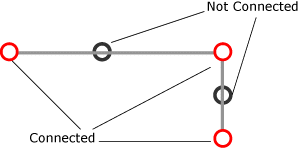
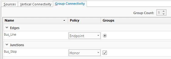
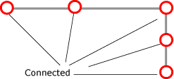
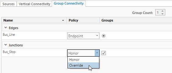
For example, the bus line that the bus stop connects to has an endpoint connectivity policy, but often you will want to place the bus stop at an intermediate vertex. To do so, you will need to set a junction policy to override the default behavior of connecting a junction to a given edge.
To override the default behavior of junctions forming at endpoints or vertices according to the edge source's connectivity policy, set the junction source's connectivity to Override. The default is to honor the edge connectivity policy.
Vertical connectivity
The connectivity of network elements can depend not only on whether they are coincident in x and y space but also on whether they share the same elevation. There are two options for modeling elevation: using elevation fields and using z-coordinate values from geometry.
Elevation fields
Elevation fields are used in the network dataset to refine the connectivity at line endpoints. They contain elevation information derived from fields on a feature class participating in the network. This is different from establishing connectivity based on z-coordinate values, in which the physical elevation information is stored on each vertex of the feature. Elevation fields apply to edge and junction sources. Edge feature sources using elevation fields have two fields to describe elevation (one for each end of the line feature).
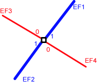
In the example below, four line features, EF1, EF2, EF3, and EF4, belong to the same connectivity group and observe endpoint connectivity. The elevation values for EF3 and EF4 are 0; the elevation values for EF1 and EF2 are 1. Hence, at the point of intersection, EF3 is connected to EF4 only (not to EF1 or EF2). Similarly, EF1 connects to EF2 only, not to EF3 or EF4. It is important to understand that the elevation fields refine the connectivity; they do not override it. Two edge elements may have the same elevation field value and may be coincident, but if they are placed in two different connectivity groups, they will not be connected.
Numerous data vendors provide elevation field data to model connectivity. The ArcGIS network dataset connectivity model can use this elevation field data to enhance connectivity. The interaction of elevation fields with the connectivity model is also vital to model special scenarios, such as bridges and tunnels.
Z-coordinate values from geometry
When source features have z-values stored in their geometry, you can create 3D networks.
Indoor pedestrian paths are often modeled with 3D networks. Consider that many hallways in a multistory building are indistinguishable in 2D, x,y space, yet they can be separated by their z-coordinate values in 3D space. Similarly, elevator shafts connect floors by moving vertically. In x,y space, elevators are points, but in 3D space, they are properly modeled as lines.
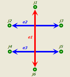
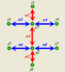
Z-coordinate values make it possible to model the connectivity of point and line features in three dimensions. Connectivity can only occur in a 3D network dataset where source features (specifically, points, line endpoints, and line vertices) share all three coordinate values: x, y, and z. The following set of images demonstrates this requirement:
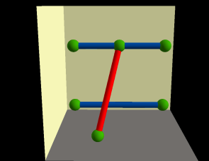
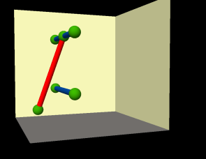
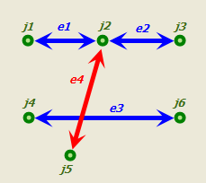
Three-dimensional networks also respect the connectivity policy settings of the connectivity group, as the following three images demonstrate:
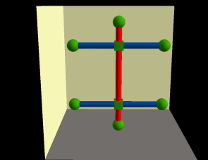
Modify elevation field vertical connectivity
Follow the steps below to modify the network's elevation fields.
- Open the Network Dataset Properties dialog box.
- Click Source Settings > Vertical Connectivity.
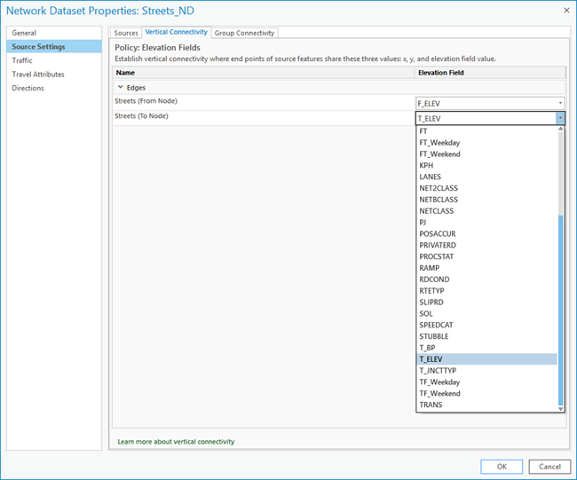
The Vertical Connectivity page appears. If your vertical connectivity policy is Policy: Elevation Fields, you will see a grid containing two rows for each edge source, one for the along direction and one for the against direction. You can use this grid to set the elevation field for each direction of each edge source.
- Click below the Elevation Field column and select the required field from the drop-down list.
The only fields that are available in the drop-down list are those with an integer data type because elevation levels are specified by integers. Any integer value is valid; that is, the field you choose can have positive, negative, and zero values.
Note:
If the network dataset you are using was not configured to use the Elevation Fields vertical connectivity policy at the time it was created, you will not be able to edit elevation fields on this page. You cannot change the vertical connectivity policy after creating your network.
- Click OK.
The change to elevation field is saved to the network dataset.
Note:
When you change any network attributes, you must build the network dataset to reestablish the connectivity, recalculate affected attributes, and update the network elements.
Modify group connectivity
Follow the steps below to modify group connectivity settings.
- Open the Network Dataset Properties dialog box.
- Click Source Settings > Group Connectivity.
- To modify the policy of a source, click in the Policy column for the source and choose the policy from the drop-down list.
Edge source connectivity can be set to End Point or Any Vertex. Junction sources can be set to Honor or Override the connectivity policy of edge sources.
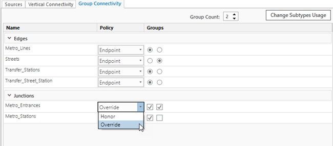
- In the Group Count box, click the up or down arrow to increase or decrease the number of connectivity groups for the network dataset, or type the group count in the box.
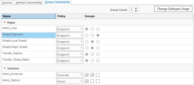
- Click the button in the relevant group column to assign an edge source to a connectivity group.
Each edge source can only belong to one group.
- Check the check box in the relevant group column to assign junctions to connectivity groups.
Each junction source can belong to multiple groups.
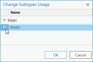
- If your feature class has subtypes, click the Change Subtypes Usage button in the upper right corner.
- Check the source feature or features to which you want to add subtypes. Connectivity can be modified per subtype on the Group
Connectivity page.
- Click OK.
The subtypes appear on the Group Connectivity page. Each subtype can be assigned to a connectivity group, with a connectivity policy.
- Check the source feature or features to which you want to add subtypes. Connectivity can be modified per subtype on the Group
Connectivity page.
- Click OK.
Edits made on the Group Connectivity page are saved to the network dataset.
Note:
When you change any network attributes, you must build the network dataset to reestablish the connectivity, recalculate affected attributes, and update the network elements.