Summary
Creates buffers around input features to a specified distance.
Usage
The Method parameter determines how buffers are constructed. There are two basic methods for constructing buffers: Euclidean and geodesic.
- Euclidean buffers measure distance in a two-dimensional Cartesian plane in which straight-line, or Euclidean, distances are calculated between two points on a flat surface (the Cartesian plane). Euclidean buffers are the more common type of buffer and work well when analyzing distances around features in a projected coordinate system that are concentrated in a relatively small area (such as one UTM zone). Euclidean buffers are referred to as planar buffers.
- Geodesic buffers account for the actual shape of the earth (an ellipsoid, or more properly, a geoid). Distances are calculated between two points on a curved surface (the geoid) as opposed to two points on a flat surface (the Cartesian plane). You should always consider creating geodesic buffers in the following circumstances:
- Your input features are dispersed (they cover multiple UTM zones, large regions, or the entire globe).
- The spatial reference (map projection) of your input features distorts distances to preserve other properties such as area.
Geodesic buffers may appear unusual on a flat map, but when displayed on a globe, these buffers will look correct.
The Method parameter determines how buffers are created.
- The planar method automatically identifies the method to use based on the coordinate system of the input features.
- If the input features have a projected coordinate system, Euclidean buffers will be created.
- If the input features have a geographic coordinate system, geodesic buffers will be created.
- Geodesic is the default. The geodesic method creates a shape-preserving geodesic buffer regardless of the input coordinate system. The shape-preserving geodesic buffer densifies the input features before creating the output geodesic buffers. This creates buffers that more closely represent the shape of the input features. If you are concerned about the shape of your buffers and how closely their shape matches the original input features, this option is recommended, particularly when your input data is in a geographic coordinate system. In some cases, this may take more time than the geodesic buffer created using the planar option, but the result is a buffer that more accurately matches the shape of the input feature.
- The planar method automatically identifies the method to use based on the coordinate system of the input features.
When using the planar method, you can improve the accuracy of buffers created with projected inputs using a projection that minimizes distance distortion, such as an Equidistant Conic or Azimuthal Equidistant projection that is geographically appropriate for your input.
When buffering polygon features, negative buffer distances can be used to create buffers inside the polygon features. Using a negative buffer distance will reduce the polygon's boundaries by the distance specified.
Note:
If the negative buffer distance is large enough to collapse the polygon to nothing, a null geometry will be generated. A warning message will appear, and no null geometry features will be written to the output dataset.
The size of the buffer can be entered using one of the following three options:
- Distance—Uses a constant value (all buffers will be the same size)
- Field—Uses values from a field (different features can have buffers of different size)
- Expression—Applies an expression to each feature (different features can have different values based on expression)
By default, the Create Buffers tool creates overlapping buffers when the buffer areas meet. When the input features are areas, the input area is included in the buffer. You can use the dissolve and multipart parameters to control how overlapping buffers are treated. The three available dissolve options are as follows:
- None—This is the default. Buffers will overlap where buffer areas meet.
- All—All of the features will be dissolved. The multipart parameter specifies whether all features will be dissolved into one feature (multipart is true) or only overlapping features will be dissolved (multipart is false).
- Fields—Features will be dissolved based on field values. You can select one or many fields, and like values will be dissolved together. The multipart parameter specifies whether all matching field features will be dissolved into one feature (multipart is true) or only overlapping matching field features will be dissolved (multipart is false).
If a field from the Input Layer parameter is used to obtain buffer distances, the field's value can be either a number (5, for example) or a number with a valid linear unit (5 kilometers, for example). If a field value is a number, it is assumed that the distance is in the linear unit of the Input Layer parameter spatial reference (unless the input layer is in a geographic coordinate system, in which case, the value is assumed to be in meters). If the linear unit specified in the field value is invalid or not recognized, the linear unit of the input features' spatial reference will be used by default.
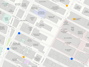
When you dissolve using All or Fields, you can calculate statistics. The statistics are only applied to the dissolving of all features or field values, they are not applied geographically (using the multipart parameter). How these options work using the six features shown in the following screen shot is described in the table below. The color denotes the field values (blue or orange) that are used for the field dissolve.
Dissolve option Multipart is false (default) Multipart is true None 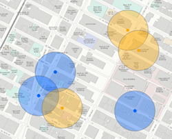
Six features are created when no dissolve is applied to buffered features. This is the default. This is the same as the standard analysis tool's Overlap option.
Multipart cannot be true when the dissolve option is None.
All 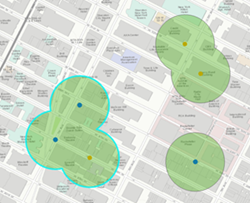
Three features are created when all values are dissolved and multipart is false. Only overlapping features are dissolved. This is the same as the standard analysis tool's Dissolve option.
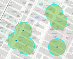
One feature is created when all values are dissolved and multipart is true. When you select this option, the result will always be one feature.
Fields 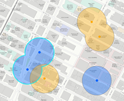
Four features are created when the dissolve is applied based on the field (here, the field is the color of input points). Only overlapping features with the same value of the specified fields are dissolved.
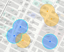
Two features are created when the dissolve is applied based on the field (here, the field is the color of input points) and multiparts are allowed. Features with the same field value will always be a single feature.
You can use a buffer type of expression to create an equation from numeric fields and mathematical operators. See Buffer expressions at ArcGIS Enterprise 10.5 and 10.5.1 or Buffer expressions at ArcGIS Enterprise10.6 and later for more information. It is assumed that numeric values in a buffer expression are in meters unless otherwise specified.
The output dataset will include a BUFF_DIST field that contains the buffer distance used to buffer each feature in the linear unit of the input features' coordinate system. If an output coordinate system is set, the BUFF_DIST units will be in that coordinate system. If the field already exists in the output, a number will be appended to the end of the field name to make it unique (for example, BUFF_DIST1).
You can improve performance of the Create Buffers tool by doing one or more of the following:
- Set the extent environment so that you only analyze data of interest.
- Use a planar buffer.
- Don't dissolve your buffer results.
- Use data that is local to where the analysis is being run.
This geoprocessing tool is powered by ArcGIS GeoAnalytics Server. Analysis is completed on your GeoAnalytics Server, and results are stored in your content in ArcGIS Enterprise.
When running GeoAnalytics Server tools, the analysis is completed on the GeoAnalytics Server. For optimal performance, make data available to the GeoAnalytics Server through feature layers hosted on your ArcGIS Enterprise portal or through big data file shares. Data that is not local to your GeoAnalytics Server will be moved to your GeoAnalytics Server before analysis begins. This means that it will take longer to run a tool, and in some cases, moving the data from ArcGIS Pro to your GeoAnalytics Server may fail. The threshold for failure depends on your network speeds, as well as the size and complexity of the data. Therefore, it is recommended that you always share your data or create a big data file share.
Learn more about sharing data to your portal
Learn more about creating a big data file share through Server Manager
Similar analysis can also be completed using the following:
- The ArcGIS Pro geoprocessing tool Buffer in the Analysis toolbox.
- The ArcGIS Pro geoprocessing tool Create Buffers in the Feature Analysis toolbox.
Syntax
arcpy.geoanalytics.CreateBuffers(input_layer, output_name, method, {buffer_type}, {buffer_field}, {buffer_distance}, {buffer_expression}, {dissolve_option}, {dissolve_fields}, {summary_fields}, {multipart}, {data_store})| Parameter | Explanation | Data Type |
input_layer | The point, polyline, or polygon features to be buffered. | Feature Set |
output_name |
The name of the output feature service. | String |
method | Specifies the method that will be used to create the buffer.
| String |
buffer_type (Optional) | Specifies how the buffer distance will be defined.
| String |
buffer_field (Optional) | The field that contains the buffer distance for each feature. If a field value is a number, it is assumed that the distance is in the linear unit of the input_layer spatial reference, unless the input_layer is in a geographic coordinate system, in which case, the value is assumed to be in meters. If the linear unit specified in the field values is invalid or not recognized, the linear unit of the input features' spatial reference will be used by default. | Field |
buffer_distance (Optional) | The distance around the input features that will be buffered. Distance can be expressed in meters, kilometers, feet, yards, miles, or nautical miles. | Linear Unit |
buffer_expression (Optional) | An equation using fields and mathematical operators that will be applied as a buffer to each feature. Fields must be numeric and the expression can include [+ - * / ] operators and multiple fields. Calculated values are applied in meters unless otherwise specified. For example, to apply a buffer that multiples a numeric field named distance in kilometers by 2 and adds 15 meters. With ArcGIS Enterprise 10.5 and 10.5.1 expressions will be formatted as the following:as_kilometers(distance) * 2 + as_meters(15). With ArcGIS Enterprise 10.6 or later, use Arcade expressions such as as_kilometers($feature["distance"]) * 2 + as_meters(15). | Calculator Expression |
dissolve_option (Optional) | Specifies the dissolve option that will be used to remove buffer overlap.
| String |
dissolve_fields [dissolve_fields,...] (Optional) | A list of one or more fields from the input features on which output buffers will be dissolved. Any buffers sharing attribute values in the listed fields will be dissolved. This option is only required when dissolve_option is LIST. | Field |
summary_fields [summary_fields,...] (Optional) | Specifies statistics that can be applied to numeric and string fields. If left empty, only count will be calculated. These statistics are only applied when dissolve_option is LIST or ALL.
| Value Table |
multipart (Optional) | Specifies whether multipart features will be created.
| Boolean |
data_store (Optional) | Specifies the ArcGIS Data Store where the output will be saved. The default is SPATIOTEMPORAL_DATA_STORE. All results stored in a spatiotemporal big data store will be stored in WGS84. Results stored in a relational data store will maintain their coordinate system.
| String |
Derived Output
| Name | Explanation | Data Type |
| output | The output buffer features. | Feature Set |
Code sample
The following Python window script demonstrates how to use the CreateBuffers tool.
#-------------------------------------------------------------------------------
# Name: CreateBuffers.py
# Description: Buffer damaged building by 300 meters

# Requirements: ArcGIS GeoAnalytics Server

# Import system modules
import arcpy

# Set local variables
inFeatures = "https://sampleserver6.arcgisonline.com/arcgis/rest/services/DamageAssessment/FeatureServer/0"
outFS = "DangerousAreas"
dataStore = "SPATIOTEMPORAL_DATA_STORE"

# Execute Create Buffers
arcpy.geoanalytics.CreateBuffers(inFeatures, outFS, "GEODESIC", "DISTANCE",
                                 None, "300 Meters", None, "ALL", None, None,
                                 "SINGLE_PART", dataStore)
Environments
- Output Coordinate System
The coordinate system that will be used for analysis. Analysis will be completed in the input coordinate system unless specified by this parameter. For GeoAnalytics Tools, final results will be stored in the spatiotemporal data store in WGS84.
Licensing information
- Basic: Requires ArcGIS GeoAnalytics Server
- Standard: Requires ArcGIS GeoAnalytics Server
- Advanced: Requires ArcGIS GeoAnalytics Server