There are two primary ways for creating routes from existing lines. You can create routes using either of the following:
- The Create Routes geoprocessing tool
- The Make Route editing tool
This topic will focus on using the Create Routes geoprocessing tool to create routes from existing lines features. To learn more about creating routes from selected line features, see Create a route using the Make Route tool.
Using the Create Routes geoprocessing tool
When using the Create Routes geoprocessing tool, the input feature classes can be any supported format. You must specify a field in the source dataset that has a route ID for each line feature. The tool merges features with the same route ID value to form a multipart line. As linear features merge, the measure accumulate in one of three ways:
- The geometric lengths of the input features accumulate the measure.
- A value stored in a measure field accumulates the measures.
- The values stored in from- and to-measure fields set the measures.
With the first two options, there are a few parameters you can decide.
- First, you can choose whether the output routes will have continuous measures when there are disjointed parts.
- Second, you can control the direction in which measures are assigned to the routes by specifying the starting measure's coordinate priority. The coordinate priority can be upper left, upper right, lower left, or lower right. These options are determined by placing the minimum bounding rectangle around the input features that are going to be merged to create one route.
You can write the output routes to a shapefile or a geodatabase feature class.
Using existing linear features to create routes
There are two scenarios for setting route measures:
- Measure values for the input features are not known.
- Measure values for the input features are known.
Measure values are not known
When route measure values are not known, you can generate them by accumulating the digitized length or a numeric attribute value of the input features. If you choose to use digitized length, the units of the output route measures will be the same as the output coordinate system (feet, meters, and so on). On the other hand, the output route measures can be any units you want when using a numeric attribute.
By creating routes in this manner, you control assigning measure direction to routes by specifying the starting measure's coordinate priority. The coordinate priority can be upper left, upper right, lower left, or lower right. These options are determined by placing the minimum bounding rectangle around the input features that will merge to create one route.
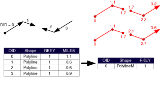
In the example below, measure values accumulate by obtaining values in the MILES field.
Note:
The digitized direction of the input features does not matter because a starting priority is given. In this example, the starting priority is lower left.

Routes with multiple, disjointed parts are supported. A route representing a road, for example, may have the same name on either side of a river. For situations like this, you can choose to ignore spatial gaps between parts when creating routes. Ignoring spatial gaps results in continuous route measures when creating a disjointed route. If you want the spatial gap incorporated in the measures, the gap distance is the straight-line distance between the parts' endpoints. The gap units will be that of the output coordinate system, which may or may not be the same as the measure units.
When creating disjointed routes, you can choose to have the measures be continuous or discontinuous. In the example below, the starting priority is lower left.

Measure values are known
When measure data already exists as attributes of linear feature inputs, you can create routes that inherit this measure information. In the following example, two fields can exist that store from- and to-mile information.
When using this method, it is important to orient each input linear feature in the direction of increasing measure to prevent routes that have measures that do not always increase.
Measure values are obtained using the values in the FR_M and TO_M fields.
Note:
In the diagram below, the digitized direction of the input features determines the direction fo the output route.
