Junction and edge objects are nonspatial network objects used to model and work with a large number of real-world features that share a common geographical space, for example, the strands inside of a fiber cable or conductors in an underground duct. This allows organizations to model their network in more detail without the need to create features with shapes for every asset.
Note:
Nonspatial junction and edge objects are available with Utility Network version 4 and later.
Network diagrams support junction and edge objects and allow you to visualize the different levels of granularity you modeled in your network. They can be used to represent and verify relations between spatial and nonspatial elements of the network.
Diagram building process
Starting with Utility Network version 4, a network diagram can represent both spatial features and nonspatial objects of a network. This means diagram junctions, diagram edges, and diagram containers in a network diagram can represent nonspatial network objects as well as spatial network features (points, polygons, and lines), structural attachments, and connectivity associations.
Network edge and junction objects are processed during diagram building in the same way as network features:
- By default. When they exist as input for diagram generation, the system creates a diagram feature for each input network object during the elementary build phase, maintains graph completeness for diagram edges, and adds containment relations between input network objects that are contents and their containers.
- Then, diagram rules can be configured on the diagram template to systematically run a trace from these initial junction or edge objects, add new nonspatial objects, discard some of them, reduce or collapse them, and so on.
Note:
Network edges that exist in the network without from and to junction objects are skipped during diagram building as much as possible. However, depending on when such an edge is encountered in the building process, it can also cause diagram generation failure.
Diagram sublayers
Edge objects are represented in diagrams as diagram edges and depicted as polylines.
Junction objects are represented in diagrams as either diagram junctions or diagram containers:
- Diagram junctions depicted as symbol points can represent content junction objects or container junction objects that are collapsed in the generated diagram.
- Diagram containers depicted as rectangle polygons can represent container junction objects when they exist in the generated diagram with all or part of their contents.
When working with Utility Network version 4 and later, any newly created diagram template includes a default diagram layer definition with line, point, and polygon layers to represent network edge and junction objects.
You can run the Create Diagram Layer Definition geoprocessing tool on your template and set the parameters in the Additional sublayers section to control the existence and type of each layer you want to represent these objects in your network diagrams.
Caution:
Diagram templates in utility networks newly upgraded to version 4 don't include a dedicated layer to represent nonspatial objects. You must either reset a default diagram layer definition or re-create a custom diagram layer definition on each existing diagram template to which these new sublayers are relevant.
Initial geometry
Any diagram layout, whether it automatically executes at diagram generation or is applied to the active diagram layer, processes the diagram features representing network features and network objects in the same way. It uses the diagram features' current geometry to compute the diagram features' new geometry.
At the end of the diagram rules phase, during network diagram building, an initial geometry is systematically applied to each diagram feature. For any diagram feature representing a network feature, this geometry most often corresponds to the geographic geometry. For diagram features representing nonspatial network objects, the system automatically computes a default geometry that adheres to the following rules:
- Any diagram edge representing a network edge object displays as a straight line between its from and to diagram junctions.
- Any diagram point junction representing a network junction object is placed at best inside the diagram polygon container representing its related container junction object or spatial container with some or all other contents.
- Any diagram polygon container representing a container junction object displays as a rectangle around all or part of its contents and is placed at best inside its own diagram polygon container.
- Any diagram polygon container representing a spatial container is placed as close as possible to its geographic position or to the center of its boundary envelope.
The following image shows network features in the geographic map:
- The three blue connection points are midspans of a distribution medium-voltage green line.
- These blue connection points are containers of network junction objects that are also midspans of three wire network edge objects.
- The green medium-voltage line is the linear container of these three wire network edge objects.

The diagram maps below show diagrams representing all or parts of these network features and their nonspatial content objects. 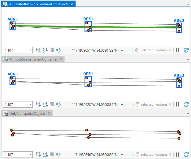
In all cases, each diagram feature geometry is initialized in the same way:
- When they remain in the generated diagrams, the connection points that are spatial containers are represented as blue polygon diagram containers. Each one is centered as closely as possible to its associated connection point location and is drawn around its contents.
- When it remains in the generated diagrams, the medium-voltage linear container is represented as a sequence of diagram edges that connect the center of their from and to blue polygon diagram containers.
- The content junction objects are represented as orange diagram junctions and positioned by default at best inside their blue polygon diagram containers.
- These junction objects are from or to junctions of wire edge objects that are represented as dark gray diagram edges.
Network diagram generation
Diagram content can be initialized from both network features and network objects.
You can open the network junction and edge object tables and click any object rows to use them as the only input for diagram generation.
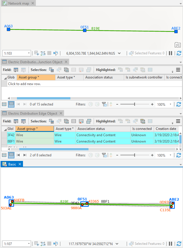
- For example, the diagram below is based on the Basic diagram template and shows two wire edge objects selected as input in the Electric Distribution Edge Object table.
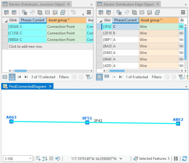
This sample diagram is based on the Basic template and shows two distribution edge objects selected as input. - The diagram below is based on a custom template configured to automatically execute a Find Connected Trace rule from the network elements specified as input and systematically remove linear containers that may exist at the end of diagram building. It shows a single junction object selected as input in the Electric Distribution Junction Object table.
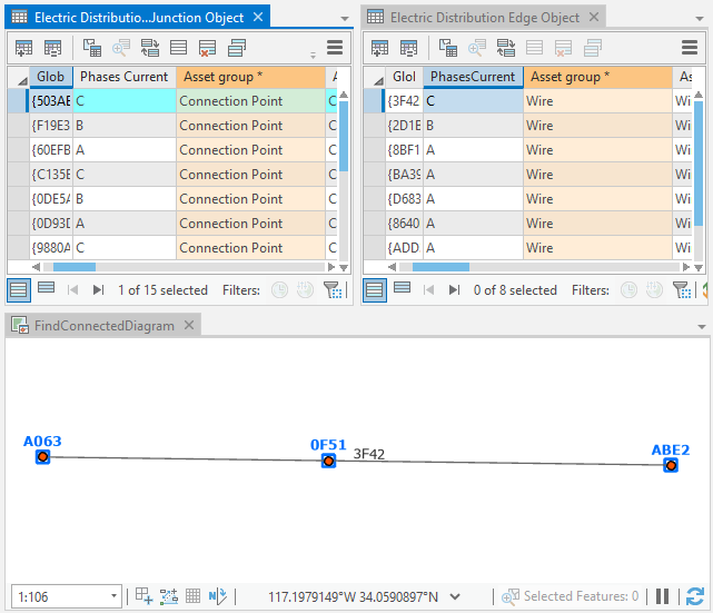
This diagram is based on a custom template generated from a single junction object selected as input.
You can also combine input to generate diagrams in which content is initialized from both features selected in the network map and objects in the network object tables. The diagram below is based on the Basic template and was generated from a set of junction objects selected in the Electric Distribution Junction Object table and the medium-voltage line feature selected in the map.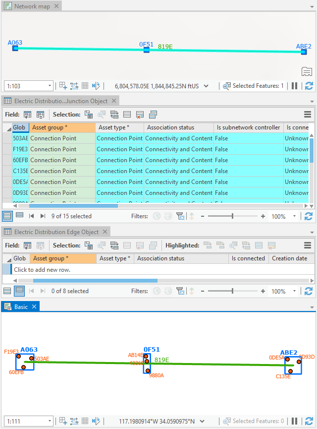
Propagate selection commands
The propagate selection commands are useful to retrieve and locate network elements that are associated with diagram features and, conversely, retrieve and locate diagram features associated with network objects.
The Apply To Maps  command can be used to retrieve network features and objects associated with a set of diagram features selected in a diagram map. It operates on both network feature layers and network object tables present in the network map.
The Apply To Diagrams  command can be used to retrieve diagram features associated with a set of network features selected in the network map or a set of network objects selected in nonspatial object tables.
For example, the images below show the result of the Apply To Maps command executed from the Basic diagram map. Since the two diagram junctions and two diagram edges selected in the diagram represent junction and edge objects, the corresponding network object rows are selected in the object tables in the network map: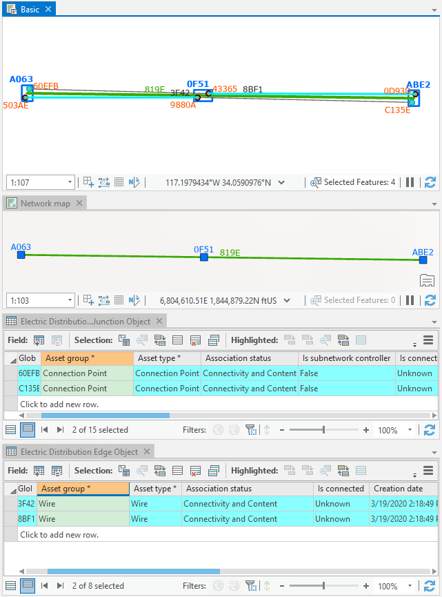
In this use case, if you want the propagation process to systematically select the spatial
container features related to the selected network objects in the object table in the network map, check the Select spatial container(s) when
propagating edge and junction objects represented in diagram
map option on the Network Diagram tab of the Network Options dialog box. The image below shows the result of the Apply To Maps command executed from the Basic diagram map.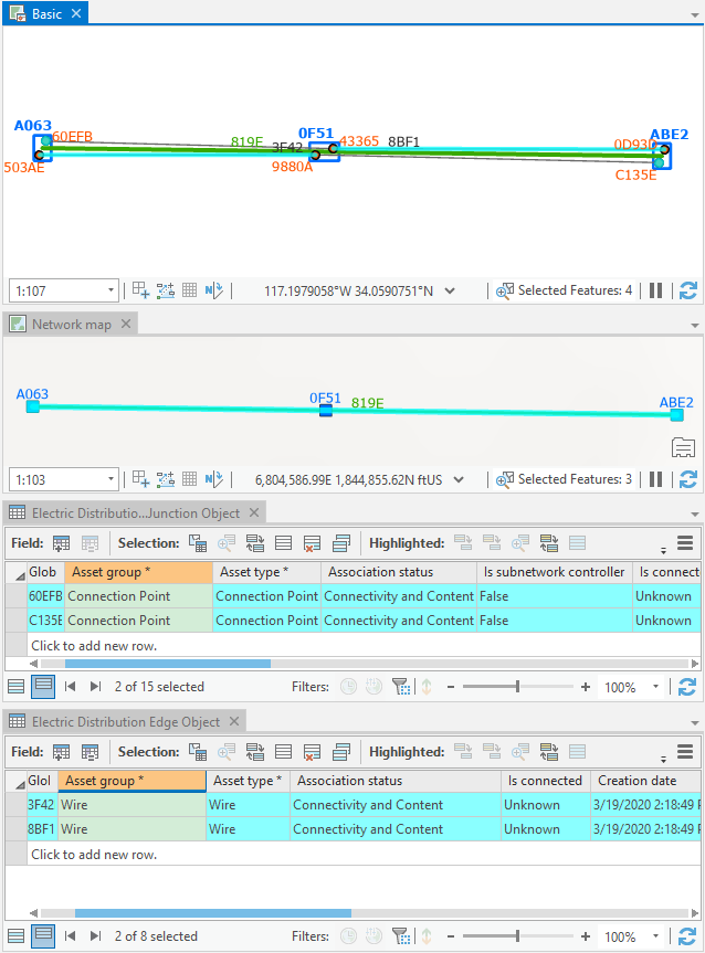
Conversely, if you select network junction or edge objects in nonspatial object tables referenced in the network map and click Apply To Diagrams, the associated diagram features are selected in any open diagrams where they are present.