All utilities manage the gathering or generation of a resource, convey it through an intermediate system of pipes or wires, and distribute that resource to the points of consumption. The following are examples:
- A water utility collects and treats water before sending it through reservoirs, tanks, and pipes to consumers.
- An electric utility generates electricity at a power-generating station and sends electric power through wires to where it is consumed.
- A gas utility gathers natural gas from a field of wells, compresses it for transmission over long distances, and regulates the pressure levels for use at homes and businesses.
Resource flows
A utility resource is delivered from a source or set of sources or collected at a sink or set of sinks. A source is an origin of the resource delivered and a sink is the destination of the gathered resource. This is configured when you add a domain network.
For a gravity-fed water collecting system, sinks of water are reservoirs and tanks. For an electric system, sources of electricity are power-generating stations and substations. For a gas system, sources of natural gas are compressor stations and regulating stations.
From each source or to each sink, the utility resource flows by pressure, gravity, or voltage until it is either impeded by an operating device such as a valve or switch, or until it reaches the point of consumption.
Sources and sinks are modeled using device features that have been set as subnetwork controllers. For a gravity-fed water collecting system, a tank or reservoir is a typical sink feature. In an electric distribution system, a circuit breaker is a typical source feature. In a gas distribution system, a town-border station is a typical source feature. These flow systems either have a set of valid source feature types or a set of valid sink feature types, but not both. Either the flow is delivered by pressure or voltage (from source features) or gathered by gravity (to sink features).
Resource flow modeling
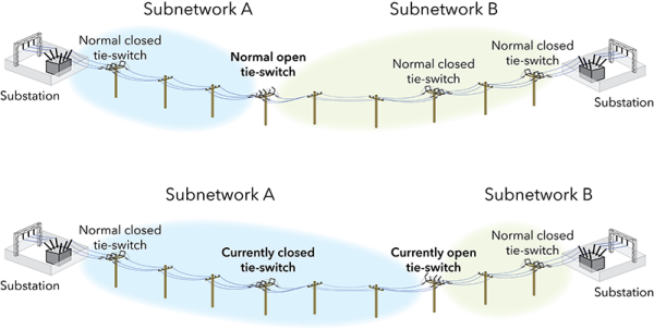
The entire utility network is subdivided into a set of zones or circuits in which that resource can flow. The flow of resources is dynamically delimited by valves and switches. The extent through which the resource can flow changes whenever a switch or valve device is changed from an open to a closed setting or vice versa.
A utility network models zones and circuits with subnetworks. A subnetwork is a set of connected features that are distributed with the utility resource from one or a few sources or to one or a few sinks. A utility system can have hundreds or thousands of subnetworks. The sources and sinks used to define the extent of a subnetwork are called subnetwork controllers.
Each subnetwork resides within a tier within a domain network and has a unique name. The name for a subnetwork is defined in the subnetwork controller, and the name of the subnetwork can be propagated to every line and device that can be traversed within the subnetwork.
A special attribute on Line, Device, and Junction feature classes is the IsConnected attribute. This attribute is used to identify features that are not traversable from any subnetwork controller. This lets you locate equipment that is either intentionally isolated in your domain network or not correctly edited.
Subnetworks are important to a utility because they give operations personnel situational awareness of the utility system's present configuration. At a glance of the map, staff can understand how gas, water, or electricity is being delivered. This information is vital when recovering from outages, optimizing the delivery of the resource, or determining which structural assets are attached to a subnetwork.
Changes to subnetworks

Because the extent of a subnetwork changes whenever an operating device is opened or closed, subnetworks are derived on demand. You can update the subnetworks in your utility network at any time. When you do, a network trace method is executed starting at the subnetwork controllers. The output of this trace method is used to update the Subnetworks table, attributes on features, and generate features within the SubnetLine feature class. This feature class contains multipart line features, representing all the connected lines for each subnetwork. These subnetwork lines can then be drawn with distinct colors to easily identify the extent of zones and circuits.