Note:
For Utility Network version 3 and earlier, see View error features.
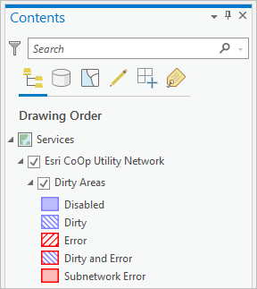
When working with a utility network, errors are generated to track inconsistencies in the network. Errors are stored in the dirty area and associations table and referenced through the Dirty Areas sublayer and Modify Associations pane.
You can use the Dirty Areas sublayer and Error Inspector pane to identify which dirty areas are associated with errors. Review dirty areas to determine the specific error associated with the network feature.
Access errors
To access errors, the utility network layer must be present in the Contents pane. If it is not, add it to your active map from the Catalog pane.
Complete the following steps to access the dirty areas sublayer:
- Expand the Utility Network layer in the Contents pane.
The Dirty Areas sublayer is displayed.

- Right-click the Dirty Areas sublayer and click Attribute Table
 to open the attribute table associated with the layer.
 - Explore the dirty areas attribute table to identify errors.
Dirty areas with an error code greater than 0 are associated with features in error.
Note:
Associations found to be in error are displayed in the Modify Associations pane with an orange indicator next to the associated feature or object. A ToolTip displays additional information for the error when you hover over the indicator in the pane.
The count of associations for nonspatial junction and edge objects in error can be found in the Network Topology section of the Network Properties tab on the Utility Network Properties dialog box as Nonspatial Objects with Errors.
Pop-ups have been configured with a custom expression that provides additional information to explore and interpret errors identified in a dirty area. In addition, the Error Inspector pane can be used to perform quality assurance workflows and review errors.
Understand error attributes
There are several attribute fields in the dirty areas table that are used to identify and work with errors using a pop-up expression or the Error Inspector pane. This information is consumed by the pop-up and Error Inspector pane to help you understand and manage error scenarios.
In addition to the attributes in the dirty areas table, the pop-up expression and Error Inspector table contain the following:
Error(s)—Provides a human readable error number and description.
For example, a record with the Error code of 10 would display in Error(s) as 10: Invalid connectivity - The edges are different subtypes and cannot connect.
The pop-up expression displays an additional attribute to provide a description of the Status field:
Status Description—Provides additional information about the operation that created the dirty area.
For example, a record with the Status value of 9 would display a Status Description of 1:Inserted/Update feature, 8:Feature error in a situation where the feature in error was modified.
Error attributes in the dirty areas table
| Field alias | Description | Example value |
|---|---|---|
Status | The status of the dirty area. A bitmask value is used to symbolize what type of operation created the dirty area. These are derived from the following:
As an example, a Status of 4 would be represented as 16 (2^4 = 16). Values are summated if multiple operations led to the creation of the dirty area or if multiple errors exist. A value 0 is displayed for the dirty area when the network topology is disabled. The Status field is not present in the Error Inspector table. | 16 |
Network Source ID | Source ID of the class in error. This displays the class name as a string using the Source ID of the network feature in error. | Electric Distribution Line |
| Feature Guid | The GUID of the network feature in error. | {C02B38E4-09A6-4BA8-83A3-E432895F7AFA} |
Error code | A bitmask value representing the error codes associated with the feature. This can represent one or more errors. An error code of 0 indicates a dirty area with no errors. As an example, an Error code of 9 would be represented as 512 (2^9 = 512). Values are summated if multiple operations led to the creation of the dirty area or if multiple errors exist. The Error code field is not present in the Error Inspector table. | 33554944 |
Error message | The Error message field provides additional contextual information associated with an error. This information is formatted to return the error, the Feature Source ID value of the destination feature, and the Global ID of the network feature or features in error. This is represented as: <error ID>, <destination feature source ID>, <GUID>. The example displays a scenario in which multiple junction features share coincident geometry; displaying error 25 followed by a FeatureSourceID of 9 (Electric Distribution Device). Finally, the Global IDs are listed for coincident features violating the rule. Note:If the error message exceeds the allotted 512 characters, the field is trimmed and a message is provided to indicate that additional rule violations exist. In this scenario, address the displayed error situation and run the validate operation again. For Error ID 9, RuleID(s) are additionally provided. | 25,9,{DBB3570D-BA76-4CEB-BB01-64E72AB9C6FD};25,9,{C487AA2E-9A4A-468A-940F-EA2136B3AE84};25,9,{A4F75E45-B911-467E-9297-4AED2AB6A08E}; |