You can add CAD data directly as feature layers in ArcGIS Pro. When CAD data is added to a map, the resulting CAD feature dataset of feature classes is accessible as a read-only feature layer. AutoCAD and MicroStation are two widely used general-purpose CAD platforms. These platforms accommodate a range of applications. ArcGIS Pro accepts data generated by AutoCAD and MicroStation-based applications and other applications that use the DGN, DWG, and DXF file formats. ArcGIS Pro also reads other feature class content in AutoCAD DWG and DXF format files from AutoCAD Civil 3D and Esri's ArcGIS for AutoCAD.
CAD data positioning
To use CAD data in ArcGIS Pro, the data must have a defined coordinate location. CAD files are required to have a valid Esri coordinate system file (.prj), and may require an optional coordinate transformation information file (.wld) to identify how the coordinates in the CAD data should be positioned on the earth's surface. ArcGIS Pro alerts you when you attempt to add CAD data that does not have a proper spatial reference. Notifications will guide you to choose the proper spatial reference, and you will be presented with tools for any necessary CAD data repositioning. To validate the positioning information for any CAD or BIM file, you can inspect the file properties in the Catalog pane and perform a coordinate positioning validation.
CAD feature datasets in the map
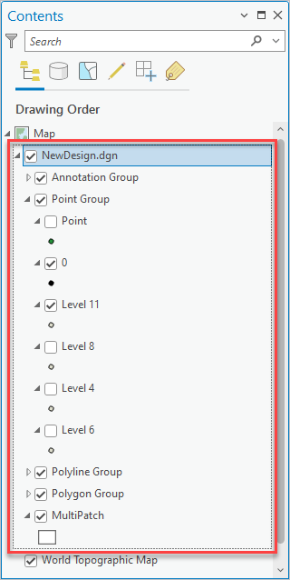
Adding the entire CAD file to the map generates a group layer of grouped feature layers. The feature layers are grouped by geometric type. Within these grouped feature layers is a series of layers established with a definition query in which the contents of each ArcGIS Pro layer in the grouping is based on the source CAD layer. The result is a group of feature layers, one feature layer within the group for each CAD layer. There are separate groups of these layers for the points, polylines, polygons, and multipatch features from the CAD file.
A CAD file as a group of grouped feature layers is shown below:

The symbology of each feature layer will attempt to mimic the symbology of the source CAD layer.
Within each geometric grouping is a feature layer that contains all the possible features of that geometric type in a single feature layer. By default, this feature layer's visibility is turned off. For example, in the polygon group, there is a feature layer named polygon that contains all the polygons from every CAD layer in a single feature layer. The visibility of these all-inclusive layers is turned off by default.
CAD feature classes in the map
Adding an individual CAD file dataset feature class to a map or scene generates a grouped collection of ArcGIS Pro layers. This is similar to the behavior adding the entire CAD drawing without the additional parent group layer for the entire drawing.
CAD data in geoprocessing
The CAD feature dataset is a valid read-only dataset that can be used by all of the ArcGIS geoprocessing tools. Similarly, the CAD file can be used in file-based geoprocessing tools. The feature classes of the CAD feature dataset are valid read-only feature classes that can be used in all of the geoprocessing tools that support read-only feature classes as input. The CAD file workspace is the system file folder for the CAD file.
The Export To CAD tool can output feature class or feature layer data to append to or create .dwg, .dxf, or .dgn file content. By default, any data that is exported to DWG or DXF format generates attributed feature classes in the mapping specification for CAD format, which is understood by the ArcGIS for AutoCAD plug-in application to AutoCAD and ArcGIS Desktop.