In the Modify Features pane, Copy Parallel  copies line features parallel or concentric to existing line features at a specified offset distance. You can copy features to one side of the selected features or create them symmetrically on both sides.
For example, you can create a trail the follows the contour of a stream, or create pavement lines symmetrically on each side of a street centerline.
- On the Edit tab, in the Features group, click Modify
 .
.The Modify Features pane appears.
- Expand Construct and click Copy Parallel
 .
.The tool opens in the pane.
- To copy specific attribute values from other feature layers to the new features, click the Editor Settings button
 , click Field Mapping
  , and configure field mapping.
To learn more, see Configure field mapping.
- Check or clear Show Preview.
Enable this setting to display a preview in the map as you configure settings.
- Click Select
 and select the line features you want to copy.
Note:
The selected features appear in the pane selection tree identified by the display field layer property setting. If the field is null, the FID field value is shown.
- In the pane, add or remove features from the selection.
- To remove a feature, right-click it and click Unselect
 .
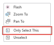
. - To keep only one feature in the selection, double-click the feature, or right-click and click Only Select This
 .
.
- To remove a feature, right-click it and click Unselect
- To create the feature on a layer that is different from the selected feature layer, do the following:
- Check Use Template.
- Click the drop-down arrow and choose a feature template.
- Check or clear the setting Keep source attribute values.
- Click Distance and specify the offset distance.
Ground to Grid
 appears when this setting is turned on.
Note:
Offsetting complex polyline features can produce complex and sometimes unexpected results. Large offset distances in particular can create self-intersecting lines as the tool copies segments perpendicular to the selected features.
- Click Repetitions and increment or type the number of times to repeat the offset operation using the current offset distance.
- Specify the side to copy the new features with respect to the direction of the selected lines.
- Both
 sides
sides - Left
 side only
 - Right
 side only
- Both
- Specify the shape of the corners.
- Mitered
 —Extends new line segments up to where they intersect
 - Rounded
 —Creates arc segments
 - Beveled
 —Adds straight segments
- Mitered
- Check or clear Remove self-intersecting loops.
Enable this setting to trim self-intersecting lines. Self- intersecting lines can occur when you specify an offset distance that is larger than can otherwise be accommodated by the resulting geometry.
- If you select two or more line features, check or clear Align the direction of connected lines.
Enable this setting to align the selected features temporarily in the same direction, indicated by the highlighted arrows. This copies the features on the same side of the selected features and in the same direction.
- Enable Copy to seperate features to create individual features for each selected feature.
- Enable Copy to a single feature to create one feature for all selected features.
Note:
Choosing this option also enables Remove self-intersecting loops.
- Click Copy.