With ArcGIS Pro, you can create maps and scenes by adding data from your computer, from a local network, or from a portal, such as your ArcGIS Online or ArcGIS Enterprise organization or ArcGIS Living Atlas of the World.
Overview
- Video length: 9:28.
- This video was created with ArcGIS Pro 2.8.
In this tutorial, you'll add data from ArcGIS Living Atlas, from the default geodatabase in your project, and from a local folder connection.
- Estimated time: 30 minutes
- Software requirements:
- ArcGIS Pro Basic
- ArcGIS Online or ArcGIS Enterprise portal connection
Note:
The quick-start tutorials are updated at each software release. For the best experience, use an online help version that matches your software version.
Open the project
You'll view the impact of potential flooding in Wellington, New Zealand, using a 2D map and a 3D scene. Your data includes hillshade and slope layers to show relief, neighborhood boundaries and buildings, and a layer showing the area susceptible to flooding in an extreme weather event.
- Start ArcGIS Pro and sign in if necessary.
- On the start page, next to the list of recent projects, click Open another project.
Note:
If you already have a project open, click the Project tab on the ribbon. In the list of side tabs, click Open. On the Open page, click Open another project
 at the top of the page.
 - On the Open Project dialog box, under Portal
 , click ArcGIS Online
  .
.Note:
If you are signed in to ArcGIS Enterprise
 , you must set your active portal to ArcGIS Online to access the tutorial data. If you can't do this, you can download the data from a browser.
 - At the top of the dialog box, in the Search box, type Add data to a project and press the Enter key.
- In the list of search results, click Add data to a project to select the project package.
Note:
If there is more than one project package with this name, select the package with the Authoritative badge
 . In the Owner column, the owner name is ArcGISProTutorials. If you don't get any results, see No search results are returned.
 - Click OK.
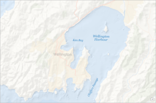
The project opens with a map centered on Wellington, New Zealand. The project also contains a local 3D scene.
Add data from ArcGIS Living Atlas of the World
The basemap layer in the Wellington map is the World Ocean basemap. It shows topographic relief for land areas at a generalized level. A relief layer with higher resolution will make it easier to see the impact of potential flooding. In addition, a more detailed layer of place-names will add context to the local geography.
You can find map layers to meet many of your needs in ArcGIS Living Atlas of the World, a curated collection of global geographic information. Maps and layers from ArcGIS Living Atlas can be added directly to ArcGIS Pro.
Note:
If you are signed in to ArcGIS Pro through an ArcGIS Enterprise portal, you have access to a smaller set of ArcGIS Living Atlas content than if you are signed in through ArcGIS Online. However, you will have access to the web layers used in this tutorial.
- On the ribbon, click the View tab. In the Windows group, click Reset Panes
 and click Reset Panes for Mapping (Default).
This ensures that the Contents and Catalog panes are open and other panes are closed.
- At the top of the Catalog pane, click the Portal tab.
Under the Portal tab are six tabs you can use to add portal items:
- My Content
 —Maps, layers, and other items you have contributed to your ArcGIS organization.
 - My Favorites
 —Portal items you have marked as favorites. (This is done from a browser connection to your portal, not from ArcGIS Pro.)
 - My Groups
 —Items shared with groups of which you are a member.
 - My Organization
 —Items shared with your ArcGIS organization, as well as items in My Content.
 - ArcGIS Online
 —Items shared publicly on ArcGIS Online, as well as items in My Organization and My Content. (If your active portal is ArcGIS Enterprise, you see ArcGIS Enterprise
  instead.)
 - Living Atlas
 —Curated items shared through ArcGIS Living Atlas of the World.
- My Content
- Click the Living Atlas tab
 .
. - Next to the search box, click Filter
 .
. - In the drop-down list, expand Categories and expand Environment. Click Elevation and bathymetry.
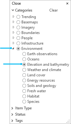
- At the top of the drop-down list, click Close.
In the Catalog pane, the list of ArcGIS Living Atlas items is filtered to show maps and layers related to elevation. Above the list of items, a box labeled Category: Elevation and bathymetry indicates the applied filter.
- In the search box, type world hillshade and press the Enter key.
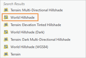
A tile layer
 named World Hillshade appears near the top of the search results. (Its position may be different in your list.)
 - Hover over the World Hillshade layer.
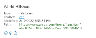
An item pop-up displays the layer's metadata. Depending on your item pop-up settings, you may also see a thumbnail image and tags, or you may not see a pop-up at all.
- Right-click the World Hillshade layer and click Add To Current Map
 .
.
By default, the map zooms to the extent of the World Hillshade layer, which covers the whole world. However, the extent is constrained by the local New Zealand map projection that has been set for the map.
- On the ribbon, click the Map tab. In the Navigate group, click Previous Extent
 to return to Wellington.
 - In the Contents pane, drag the World Hillshade layer beneath the World Ocean Base layer.
Partial transparency has been applied to the World Ocean Base layer, so the World Hillshade layer shows through it. You can turn the World Hillshade layer off and on in the Contents pane to see the difference in terrain detail.
- In the Catalog pane, click Clear filters.
- In the search box, click Delete
 to clear the current search terms.
 - In the search box, type light gray canvas reference and press the Enter key.
A vector tile layer
 named Light Gray Canvas Reference (Local Language) appears at or near the top of the search results.
 - Right-click the Light Gray Canvas Reference (Local Language) layer and click Add To Current Map
 .
. - In the Contents pane, right-click the World Ocean Reference layer and click Remove
 .
.Now you have just one layer of place-names in the map.
- In the Contents pane, click the Light Gray Canvas Reference (Local Language) layer to select it.
- On the ribbon, click the Vector Tile Layer tab.
- In the Effects group, in the Transparency box
 , highlight the default value of 0.0% and type 25. Press the Enter key.
Tip:
Alternatively, click the Transparency drop-down arrow and set the value with the slider.
At very large map scales, the place-names are not necessary. You'll set a visibility range so the layer doesn't display when you zoom in beyond a specified scale.
- In the Visibility Range group, click the drop-down arrow next to Maximum Scale
 and click 1:24,000.
The place-names won't display when you zoom in closer than 1:24,000.
Tip:
If you don't have this value in your drop-down list, you can type it in the text box.
- In the Contents pane, right-click the Light Gray Canvas Reference (Local Language) layer and click Properties
 .
. - On the Layer Properties dialog box, on the General tab, change the name of the layer to Reference. Click OK.
- On the Quick Access Toolbar, click Save Project
 .
.
Add data from a geodatabase
Every ArcGIS Pro project has a default geodatabase for storing project data. In a new project, the default geodatabase is empty until you add data to it—for example, by running a geoprocessing tool. The default geodatabase in this project already contains a few datasets.
- In the Catalog pane, click the Project tab. Browse to Databases > add_data_to_a_project.gdb.
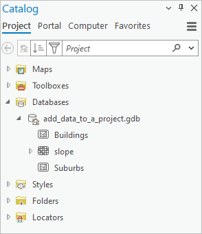
The geodatabase contains two feature classes (Buildings and Suburbs) and a raster dataset (slope). You'll add the Suburbs data to the map.
- Right-click Suburbs and click Add To Current Map
 .
.Tip:
You can also drag the layer from the Catalog pane to the map.
- In the Contents pane, drag the Suburbs layer under the Reference layer.
- Right-click the Suburbs layer and click Zoom To Layer
 .
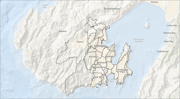
.The Suburbs layer has a solid fill color that prevents you from seeing the basemap under it. You'll change the symbol fill color and outline.
- In the Contents pane, right-click the Suburbs layer and click Symbology
 .
.The Symbology pane appears. At the top of the pane, the Primary symbology tab
 is selected. The primary symbology method is Single Symbol, which means that all features in the layer have the same symbol.
 - In the Symbology pane, click the symbol for the layer.
The pane changes to show symbol formatting options. On the Gallery tab, you can browse or search for symbols. On the Properties tab, you can change the properties of the current symbol.
- In the Symbology pane, under Format Polygon Symbol, click the Properties tab.
- On the Symbol tab
 , under Appearance, click the Color drop-down arrow and click No color.
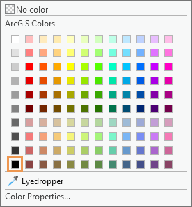
 - Click the Outline color drop-down arrow and click Black.
- At the bottom of the pane, click Apply.
Add data from a folder
You can add data to your project from any folder, database, or other resource to which you make a connection. Every project has a default connection to its home folder—the folder in which the project file, default geodatabase, and default toolbox are stored. In this project, the home folder also contains a shapefile representing the flood risk zone for Wellington.
Note:
You can add data from the Computer tab in the Catalog pane without making a folder connection to the location.
- In the Catalog pane, browse to Folders > Add_data_to_a_project > commondata > userdata.
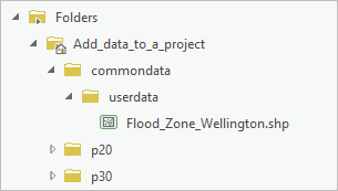
The userdata folder contains a shapefile named Flood_Zone_Wellington.shp.
Note:
In a project package, files that can't be stored in a geodatabase, such as shapefiles, CSV files, and text files, are included as attachments. Within the project package folder structure, attachments are stored in the commondata > userdata folder.
- Right-click Flood_Zone_Wellington.shp and click Add To Current Map
 .
. - In the Contents pane, drag the Flood_Zone_Wellington layer under the Suburbs layer.
- In the Contents pane, click the symbol for the Flood_Zone_Wellington layer.
Tip:
Clicking a symbol in the Contents pane opens the Symbology pane to symbol formatting options.
- In the Symbology pane, under Format Polygon Symbol, click the Properties tab if necessary.
- On the Symbol tab
 , under Appearance, click the Color drop-down arrow and click Big Sky Blue.
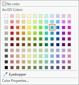
- In the Outline width box, highlight the default value and type 0. Press the Enter key and click Apply.
The map shows that most of the flood risk zone lies within one suburb.
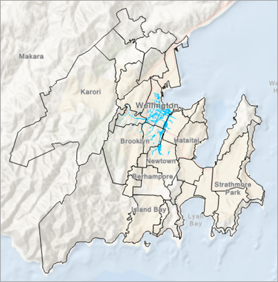
- In the Contents pane, right-click the Flood_Zone_Wellington layer and click Zoom To Layer
 .
.The place-names from the Reference layer no longer display because the map scale is larger than 1:24,000.
Tip:
If you still see the labels, use the mouse wheel to zoom in closer. Alternatively, click the Map tab on the ribbon. In the Navigate group, click Fixed Zoom In
 as needed. You can also type a scale value in the scale box at the bottom of the view.
 - On the map, click the suburb containing most of the flood risk zone.
The Pop-up pane appears and identifies the suburb as Te Aro.
Note:
By default, pop-ups are displayed for the topmost layer in the Contents pane (excluding reference layers). You can change this setting by clicking the Explore tool
 drop-down arrow on the Map tab.
 - Close the Pop-up pane.
- On the Quick Access Toolbar, click Save Project
 .
.
Visualize data in 3D
You'll look at the data in the Wellington 3D scene to visualize the potential impact of flooding in the Te Aro suburb. The scene contains a topographic basemap and a layer of buildings. You'll copy and paste the flood zone layer from the map. You'll also add a slope dataset from the default geodatabase.
- In the Contents pane, right-click the Flood_Zone_Wellington layer and click Copy
 .
. - Click the Wellington 3D view tab to make the scene active.
- In the Contents pane, under Drawing Order, right-click the Wellington 3D scene name and click Paste
 .
.The layer is added to the scene and appears in the Contents pane under the 2D Layers heading.
Note:
A layer appears under the 3D Layers heading if 3D drawing properties, such as extrusion, have been applied to it, or if its source data stores elevation values (z-values). Otherwise, it appears under the 2D Layers heading.
- In the Catalog pane, browse to Databases > add_data_to_a_project.gdb. Drag the slope dataset onto the scene.
The default layer symbology is a black-to-white color scheme. You'll change it to a conventional color scheme for slope.
- In the Contents pane, click the slope layer symbol (the black-to-white color scheme).
- In the Symbology pane, click the Color scheme drop-down arrow. At the bottom of the drop-down list, check the Show names check box.
Names appear above their associated color schemes.
- Find the Slope color scheme (bright green to bright red) and click it.
The symbology is applied to the layer.
The project contains two bookmarks to help you explore the flood zone.
- On the ribbon, click the Map tab if necessary. In the Navigate group, click Bookmarks
 . Under Wellington 3D Bookmarks, click Flood View 1.
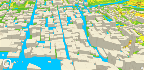
The scene zooms to the bookmark. In the lower left corner of the view, notice the direction of the north arrow on the on-screen navigator
 . Your view faces south, or slightly southwest. It looks like a flood would affect most of the buildings in the foreground of the view.
 - Click Bookmarks
 again and click Flood View 2.
This view shows how floodwater may flow through the landscape at the western end of the suburb. Use the Explore tool
 on the Map tab or the on-screen navigator to continue exploring the suburb.
 - On the Quick Access Toolbar, click Save Project
 .
.
For many projects, you need to search for data to complete your mapping and analysis. In addition to ArcGIS Living Atlas of the World, you can search your portal and ArcGIS Online for maps and layers. You can also search ArcGIS Hub to find open-access data from thousands of organizations that share their authoritative data.
