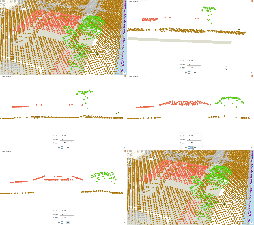
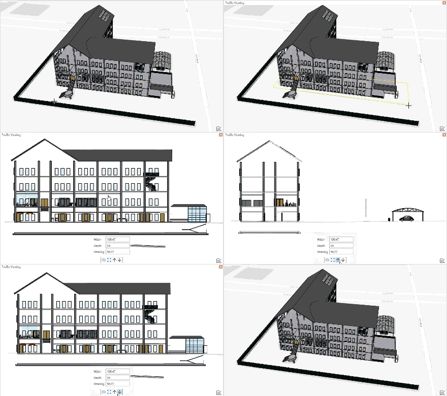
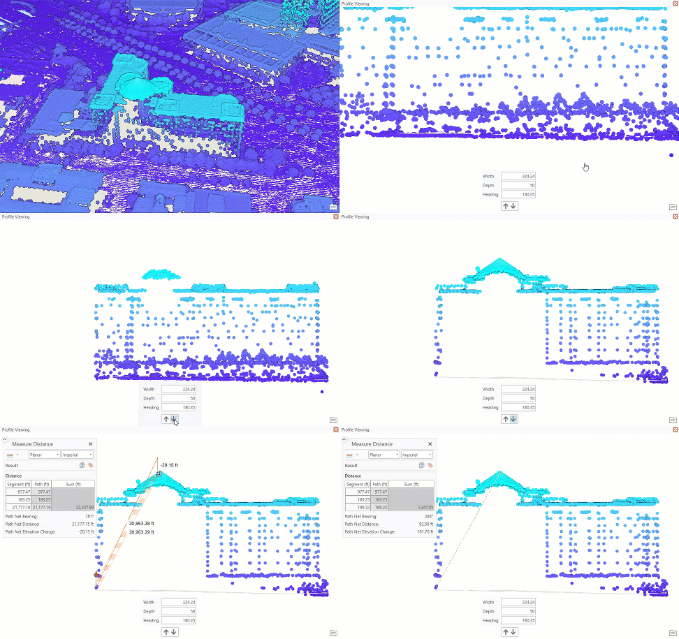
Profile viewing makes it easier to select, measure, or identify features in 3D. When features are stacked vertically, profile viewing helps provide a clearer depiction. This temporary display state is available in any scene but is particularly useful for scenes containing building interiors or lidar data. For example, you can edit the classification codes for lidar data and view architectural-style cross-sections of a building. Profile viewing works on all types of data and surfaces.
Profile viewing shifts the camera automatically to look at the data from a side-on viewpoint and adjusts the current view in the following ways:
- The display is clipped into a vertical slice.
- The scene view switches from the default drawing mode to parallel drawing mode so there is no perspective distortion in the view.
- Planar navigation activates so you can pan across the scene rather than through it.
The tools and settings for profile viewing are on the View tab in the Profile Viewing group. Projects that are saved with scenes displayed using profile viewing reopen in the same state. The profile viewing controls are also accessible on the Classification tab when working directly with LAS datasets.
Profile viewing in a scene
To use profile viewing, you must have a 3D scene open. You start by constructing a profile line in the area of interest. Creating a profile is similar to creating a two-point line feature. By default, the profile line autocompletes and updates the view extent into the profile viewing state. The extent is clipped to define the profile area and the camera navigates to an orthogonal viewpoint. The view automatically switches to parallel drawing mode so there is no perspective distortion in the view. Planar navigation is activated so you pan across the view rather than through it.
Optionally, you can set the line creation to not autocomplete. With autocomplete off, you can use editing handles in the scene to manually scale and reposition the profile extent. You must manually click Finish Profile  in the on-screen settings control to apply the profile line and update the display.
To create a profile view of the scene, do the following:
- On the View tab, in the Profile Viewing group, review or set the Depth value.
This is the depth of the viewing slice. The larger the depth value, the more content that displays in the profile view. Larger values increase the potential for features up close to obscure any content farther away. Smaller depth values are recommended.
- Click the Create drop-down menu and confirm Auto-complete is checked. By default, Auto-complete is checked so that the profile line sketch is automatically completed after you click the endpoint. If you uncheck Auto-complete, the profile line stays in an edit-sketch mode and can be repositioned around the view before it is applied.
- Click Create
 to activate the Create Profile tool.
 - Move the pointer into the view. Click once to set the starting point of the profile line. Click again to set the endpoint of the profile line.
The text Profile Viewing appears at the top of the scene to indicate you are currently in a profile viewing state.
- To reset the camera to its starting profile position, click Full Extent
 on the View tab in the Profile Viewing group.
 - To exit profile viewing mode, click the Close button
 in the upper right of the scene view in the same banner where the Profile Viewing text appears.
 The camera returns to its previous viewpoint and exits both planar navigation mode and parallel viewing mode.
Adjust the profile view
You can adjust the location and properties of the active profile view without having to exit profile viewing and define the profile line again. This is useful for small changes to the depth, width, or angle of the profile view, or for moving the profile view display through the scene in a series of fixed distance steps.
The options for interacting with profile viewing on the View tab include the following:
| Command | Description |
|---|---|
Full Extent | Returns the camera to the front of the profile line. This command is useful if you navigate away from your content. Depending on the aspect ratio of the data inside the profile view, you may need to zoom out to see all the content from this viewpoint. |
Settings | Allows you to show or hide the on-screen settings for adjusting the profile view. |
Depth | Sets the depth to use when creating a profile view. Larger values contain more content but potentially contain more elements that obscure each other. Smaller values are recommended. The value is stored as a user setting and saves until you change it. |
Move Away | Steps the position of the profile view away from the front of the profile by its current depth value. |
Move Towards | Steps the position of the profile view toward the front of the profile by its current depth value. |
The options for interacting with profile viewing using the on-screen control, which can be turned on using the Settings button  , include the following:
| Command | Description |
|---|---|
Width | View or update the value for the width of the current profile view. Increasing the value widens the amount of content shown across the profile view. The camera position does not change, so you may need to zoom out to see the additional content. |
Depth | View or update the depth value of the current profile view. Increasing this value includes more content in the current profile viewing extent and increases the likelihood that near content obscures far content. |
Heading | View or update the azimuthal angle of the current profile view. Changing this value rotates the profile view around its centerpoint and moves the camera to maintain an orthogonal view direction. |
Move Away | Steps the position of the profile view away from the current viewpoint by its current depth value. |
Move Towards | Steps the position of the profile view toward the current viewpoint by its current depth value. |
Move and Rotate Profile | Only available when line creation is set to not autocomplete. Rotate the green handle to change the heading of the profile line. Drag the green arrow to adjust the z-value. The z-value is used to center the view when Full Extent |
Scale Profile | Only available when line creation is set to not autocomplete. Drag the spherical anchor points to widen or shrink the profile line's width and depth values. |
Finish Profile | Only available when line creation is set to not autocomplete. Applies the profile line and updates the display. |
Example workflows for profile viewing
The following examples demonstrate two ways profile viewing can be used.
Edit classification codes for lidar data
Lidar points have classification codes, such as ground, building, or medium vegetation, and these values can be missing or incorrect. Profile viewing can be used to view the lidar in a way that facilitates the selection and updating of class codes for individual points. To edit classification codes, select the LAS dataset layer in the Contents pane and click the Classification tab. The Profile Viewing controls are accessible on the Classification tab to create a profile view. Use interactive selection methods and the Classification Codes drop-down menu in the Interactive Edit group to choose a new classification code for the selected points.

Create profile images of building model data
Architectural designs often include profile views of the principal sides of a building. Profile viewing can be used to view and export images along these lines. Navigate or use the Move Away  and Move Towards
  commands to step through your profile. On the Share tab, click Export Map to File
  to save an image file of the current display.

Use the Measure tool while profile viewing
Profile viewing makes it easier to measure in 3D by focusing an area of interest and displaying stacked features. This can be useful for dense lidar data. To measure vertically, it is recommended that you use the Measure Distance tool  . In a scene it returns results for the direct distance between the end points, as well as values for vertical and horizontal offset distances. Measure also supports snapping so you can accurately create end points where you want to measure from and to.


