The Build Frames & Cameras Tables tool generates frames and cameras tables using an image exterior orientation file and camera calibration information. The frames and cameras tables can be used to create a mosaic dataset, Ortho mapping, or Reality mapping workspace with the frame camera raster type or scanned imagery.
Build the frames and cameras tables
The Build Frames & Cameras Tables tool converts your exterior orientation files and camera information into Esri frames and cameras tables, respectively. The tool must be added to a location on the project ribbon or to the Quick Access Toolbar. Follow the steps below to add the tool to the ribbon or Quick Access Toolbar.
You can add multiple exterior orientation files using the Add button at the top of the dialog. The resulting output will be saved as a separate Esri frames table. If you only want to generate a cameras table, use the Export  tool at the top of the Cameras dialog.
Add the Build Frames and Cameras Tables tool to ArcGIS Pro.
The Build Frames and Cameras Tables tool must be added to a location on the project ribbon or to the Quick Access Toolbar. This customization is stored in your user directory and applies to any project you open.
- Click Project > Options > Customize the Ribbon.
- Under Choose commands from, select All Commands.
- Search for and select the Build Frames and Cameras Tables tool from the list of commands.
- Select the ribbon tab and group where you want to add the tool from the list of Tabs on the right.
- Click the Add button.
To add a tool to the Quick Access Toolbar, complete the following steps:
- Click Project > Options > Quick Access Toolbar.
- Under Choose commands from, select All Commands.
- Search for and select the Build Frames and Cameras Tables tool from the list of commands.
- Click the Add button.
Create the frames table
Follow the steps below to create the Esri frames table. Click the Build Frames and Cameras Tables tool you added to ArcGIS Pro to open the tool.
- Enter your Exterior Orientation File.
Supported formats are .txt, .csv, .tab, or .eo files. Parameters will appear so you can define how your exterior orientation file should be parsed to convert it to an Esri frames table. The following information is required in the exterior orientation file: Image Name, Perspective X, Perspective Y, Perspective Z, Omega, Phi, Kappa. See the Frames table schema for more information. The field names in your file do not have to match the field names listed in the Frames table schema, since you will be mapping your fields in the steps below. If your data has headers, select the Data has headers option on the pane if not already checked.
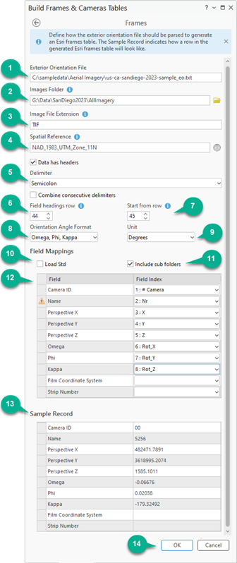
- Browse to and select your aerial digital or scanned imagery folder.
- Type the image format extension of your images. For example, type TIF, JPG, MRF, and so on.
- Specify the spatial reference of your perspective points.
- Select the delimiter that will be used to parse your Exterior Orientation File. You may choose to combine consecutive delimiters if necessary.
- For Field headings row, enter the row number that identifies where the exterior orientation field headings start.
If you want to skip a number of images, specify the row number from which to begin parsing the file.
- For Start from row, enter the row number that identifies the beginning of the exterior orientation information.
- Select the appropriate Orientation Angle Format from the drop-down list.
- Omega, Phi, Kappa (default)
- Phi, Omega, Kappa
- Roll, Pitch, Yaw (Fixed Wing)
- Roll, Pitch, Yaw (Rotary)
- Select the Unit associated with the selected Orientation Angle Format from the drop-down list.
- Optionally, check the box next to Load Std (standard deviation) if the exterior orientation file contains this type of information.
When selected, the following six fields will be added to the Field Mappings table.
- Std X—Standard deviation for the perspective X, or easting coordinate.
- Std Y—Standard deviation for the perspective Y. or northing coordinate.
- Std Z—Standard deviation for the perspective Z, or height coordinate.
- Std Omega—Standard deviation for the omega angle.
- Std Phi—Standard deviation for the phi angle.
- Std Kappa—Standard deviation for the kappa angle.
- Imagery stored in sub-folders will be processed when Include sub-folders option is checked.
- Define your field mappings as described in the Frames table schema.
Note:
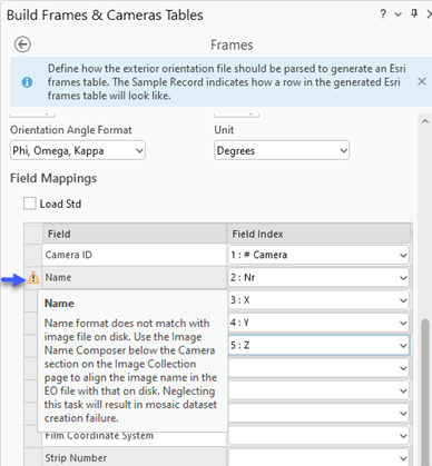
The Name field is required in this tool, though it is an optional field in the frames table itself. This is because the Name field is combined with the Images Folder and Image Format to identify the full path to each image in your collection. Because of this, the Name field must point to a column in your exterior orientation file with image names that are associated with or match the exact names of the images in the Images Folder.
For scenarios where the image name in the exterior orientation file does not match that on disk, a warning flag
 will appear to the left of Name in Field Mappings section to highlight this issue. Once you have completed defining the parameters in the Frames window, the Image Name Composer will become accessible (after entering or importing camera calibration information) on the Source Data page, that can be used to link the name in the exterior orientation file with that on disk. See Image Name Composer below for additional information.
 - Review the Sample Record for accuracy and completeness.
- Click OK to accept the settings for the Build Frames and Cameras Tables window.
The Source Data window will appear.
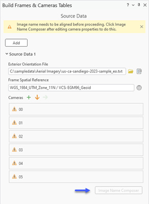
Create the cameras table
Follow the steps below to define parameters for your cameras table in order to compute the camera model and interior orientation.
Note:
Once you have completed defining the parameters in the Frames window, if the ingested exterior orientation file has multi-camera ID’s, they will be listed in the Cameras section of the Source Data page. It is recommended that you delete cameras not required for your project prior to entering camera calibration information. This can be done by hovering the mouse pointer over the camera of interest and selecting the delete option on the right.

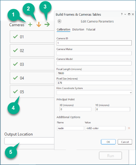
- Manually enter individual camera information by selecting the Add
 tool. You will be prompted to provide information on the Calibration, Distortion, and Fiducial tabs. The following information on the Calibration tab is required: Camera ID, Focal Length, Pixel Size, and Principal Point; all other parameters are optional. For detailed information on the parameters and information that can be input in the camera model, see the Cameras table schema.
 - Alternatively, select the Import
 tool to browse to an existing .txt or .csv file containing the cameras information with the fields described in the Cameras table schema.
 - Once you have completed manually entering the cameras information, the Export
 tool can be used to save a copy of the file for future use.
 - The cameras will be listed according to their CameraID. A green check mark next to the CameraID indicates that the required information has been provided. A caution symbol indicates there are incorrect or missing fields.
- Browse to and select an output folder location, then click Run.
The Esri cameras and frames tables will be created in the output folder location.
Note:
You can add multiple exterior orientation files using the Add button at the top of the dialog. The resulting output will be saved as a separate Esri frames table.
Image Name Composer
In scenarios where the image name in the exterior orientation file does not match that on disk, the Image Name Composer enables the formulation of matching image names to support the creation of a Frames table. Matching image names can be formulated using information in the image name field and other sections of the exterior orientation file.
For example, using the exterior orientation file below, you can see that the image in the name field (Nr) is different from that of the image name on disk for one nadir imagery (5256-lvl02-color.tif). Using the Image Name Composer, a proper image name can be formulated by combining the information in the Nr field with the information in the Camera 01 Type field (Lvl02-Color), resulting in a composed name of 5256-Lvl02-Color.
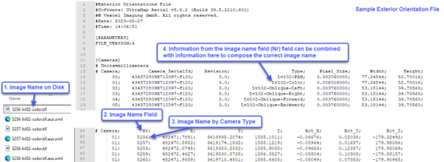
Access to the Image Name Composer will only be available under the following conditions:
- The image name in the exterior orientation file ingested in the Frames tool is different from the image name on disk. In this scenario, a warning flag
 will be displayed beside the Name field in the Field Mappings section of on the Frames page.
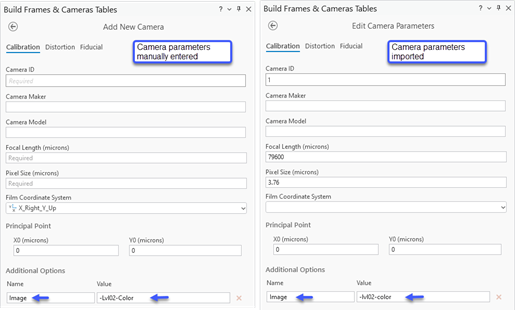
- Information to compose the image name is manually entered or imported, for each camera, into the Additional Options section of the Add New Camera window, or Edit Camera Parameters window.
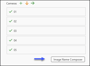
- If the above conditions are not satisfied, the Image Name Composer option will not be enabled. In scenarios where there are no discrepancies between the image name on disk and image name in the exterior orientation file, the Image Name Composer option will not be enabled in the Source Data window.
To use the Image Name Composer to formulate the correct image name for use in the Frames table, follow the steps below.
Note:
The following instructions assume that all the parameters required for the frames table has already been defined in the Frames window.
- On the Source Data page, in the Cameras section, click the Add New Camera
 button to manually enter camera parameters for each camera. Alternatively, Import
  the parameters from an existing camera file on disk.
 - In the Additional Options section, for each camera, enter appropriate values for Name field and Value field, then click OK to accept the changes. For example, using the information in the sample exterior orientation file depicted above, the following information could be entered into the Name and Value fields for each camera.
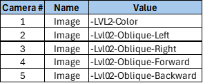
- Once the parameters for each camera have been entered, the Image Name Composer button will become active. Click it to open the Image Name Composer window. The menu options available in the window includes, Add
 a column, Delete
  the last column, Apply
  selected record format to all rows, and Reset
  selected record.
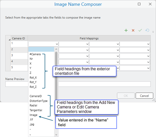
- For Camera ID 1, click the drop-down menu in the left-most box, and select Nr.
- Click in the box to the right of the previously selected box, and select Image from the drop-down list. The associated image name is displayed in the Name Preview section.
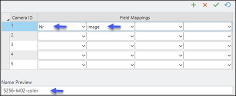
- With camera ID 1 selected, click Apply Format
 button, then click Yes to confirm the formatting. The values for camera ID 1, will be copied to all remaining cameras.
 - Click each camera ID and verify the accuracy of the associated image name in the Name Preview section.
- Click OK to accept the inputs, and close the Image Name Composer window.
- For Output Location click the Browse button, navigate to the folder on disk to store the tables to be created, then click OK.
- Click Run to create and export the Frames and Cameras table.