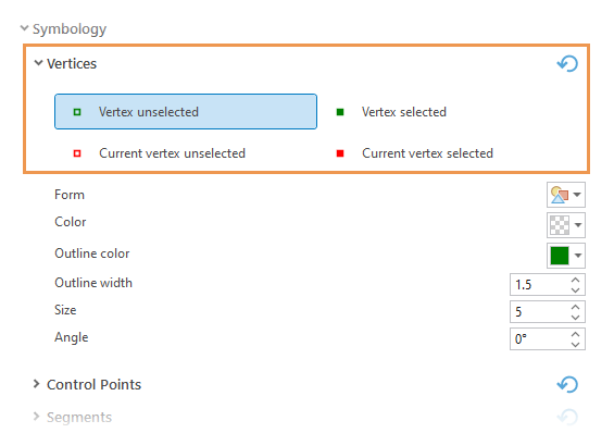
Application editing options for sketch symbology include settings for vertices, segments, and control points that symbolize unfinished sketch geometry. These options are available on the Options dialog box on the Editing side tab.
Note:
Control points are special vertices that are used to apply symbol effects to line or polygon features. For steps to enable control points or customize their appearance, see Enable control points or change symbology.
To customize the appearance of sketch vertices or segments, complete the following steps:
- Click the ribbon Edit tab. In the Manage Edits group, click the Options dialog box launcher
 .
.The Options dialog box appears.
- Click the Editing side tab and expand Symbology.
- Expand Vertices, choose a vertex symbol for the selected or unselected state, and customize the settings.

Form
Click the drop-down arrow and choose a symbol.
Color
Click the drop-down arrow and choose a color.
Outline color
Click the drop-down arrow and choose an outline color.
Outline width
Click the text box, and type a width value or click the control arrows.
Size
Click the text box and type a point size or click the control arrows.
Angle
Click the text box and type an angle value or click the control arrows.
To reset the values to the default settings, click Reset to default
 .
. - Expand Segments and customize the settings:
Primary Color
Click the drop-down arrow and choose a color.
Secondary Color
Check the check box, click the drop-down arrow, and choose a color.
Width
Click the text box and type a width value or click the control arrows.
To reset the values to the default settings, click Reset to default
 .
. - Click OK.
The settings are saved and the dialog box closes.