Overview
- Video length: 2:35
- This video was created with ArcGIS Pro 2.3.
3D is an integral part of ArcGIS Pro. Any 2D map can be converted to a 3D scene for data visualization, exploration, or analysis. In this tutorial, you'll convert a 2D map to a 3D scene and work with its 3D viewing properties.
- Estimated time: 30 minutes
- Software requirements: ArcGIS Pro
Note:
The tutorial steps in the online help reflect the look and capabilities of the current software release. If you have an earlier software version, use the offline help system to open the tutorial. To switch from the online to the offline help system, see Set the help source in the topic About ArcGIS Pro help. If you don't have ArcGIS Pro, you can sign up for an ArcGIS Pro free trial.
Open the project
Your study area is the Kelburn suburb of Wellington, New Zealand. The starting map will be familiar to you if you completed the Import an ArcMap document tutorial.
- Start ArcGIS Pro and sign in if necessary.
- On the start page, under your recent projects, click Open another project.
Note:
If you already have a project open, click the Project tab on the ribbon. In the list of menu items on the left, click Open. On the Open page, click Portal and click Open another project at the bottom of the page.
- On the Open Project dialog box, under Portal
 , click ArcGIS Online
  .
.Note:
If you see ArcGIS Enterprise
 listed instead, you must set your active portal to ArcGIS Online or download the tutorial data from a browser. Learn more about how to access the quick-start tutorials.
 - At the top of the dialog box, in the Search box, type Convert a map to a scene tutorial and press Enter.
- In the list of search results, click Convert a map to a scene to select the project package.
Note:
If there is more than one project package with this name, look at the Owner column. Select the item with the owner name ArcGISProTutorials. If no search results are returned, see Access the quick-start tutorials.
- Click OK.
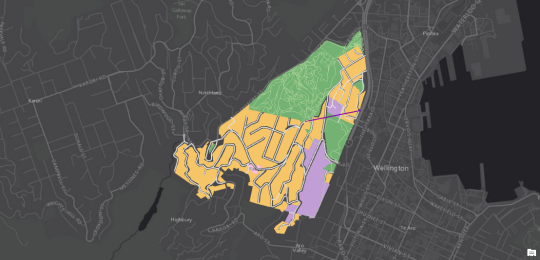
The project opens with a map view of the Kelburn suburb. Layers representing walking paths, roads, and zoning are displayed on a dark gray basemap.
By default, project packages are unpacked to your <User Documents>\ArcGIS\Packages folder. You can change the default location in the Share and download options.
Create a scene from the map
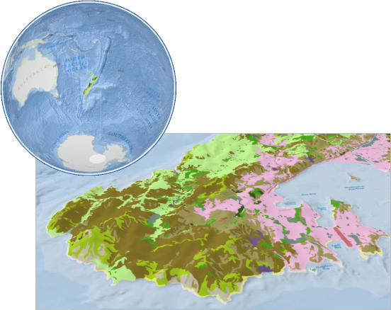
In ArcGIS Pro, a 3D map is called a scene. A scene can be viewed in either global or local mode. In global mode, the earth is drawn as a globe and your viewpoint is usually thousands of kilometers from the data. This view is best for very large study areas. In local mode, the earth is drawn in perspective and your viewpoint is usually tens of kilometers from the data. This view is best for small study areas.
In this project, your area of interest is very small. You'll convert the map to a local scene.
- On the ribbon, click the View tab. In the Windows group, click Reset Panes
 and click Reset Panes for Mapping.
This ensures that the Contents and Catalog panes are open and that other panes are closed.
- On the View tab, in the View group, click Convert
 . On the drop-down menu, click To Local Scene
  .
.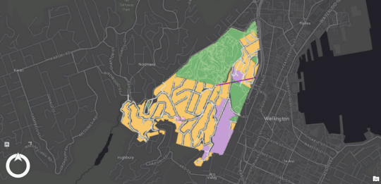
The map is converted to a scene named Kelburn_3D. The local scene icon
 appears on the scene's view tab.
Note:
You can view any scene as a global scene or a local scene by clicking the Global button
 or the Local button
  in the View group on the View tab.
Local scenes support projected coordinate systems. For example, this scene uses the NZGD 2000 New Zealand Transverse Mercator coordinate system (as does the 2D Kelburn map). Global scenes don't support projected coordinate systems. They use the WGS 1984 geographic coordinate system.
In the Contents pane, the map layers have been copied to the scene. At the bottom of the pane is an Elevation Surfaces category with a ground layer named WorldElevation3D/Terrain3D. (Expand the Ground heading to see the layer.) This layer provides elevation values for the 2D map layers so they draw in 3D space.

WorldElevation3D/Terrain3D is a worldwide elevation surface. It's a composite of many elevation maps with varying resolution, or detail. In New Zealand, the resolution is approximately 31 meters, meaning there is one elevation value for every 961 square meters of area (31 meters squared).
To see the WorldElevation3D/Terrain3D resolution and data source for any part of the world, open the Elevation Coverage Map.
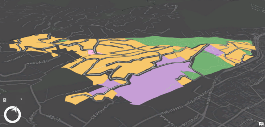
From the current perspective, the scene doesn't look very 3D, but you'll take a few moments to explore it from other perspectives.
- On the ribbon, click the Map tab. In the Navigate group, make sure the Explore tool
 is selected.
 - Use the mouse buttons and mouse wheel to zoom, pan, tilt, and rotate the scene. Alternatively, use the on-screen navigator
 in the lower left corner of the scene.
If you get disoriented, use Bookmarks
 on the Map tab to return to a familiar perspective. For help with 3D navigation, see Navigation in 3D or the Navigate maps and scenes quick-start tutorial.
The dark gray basemap tends to obscure the 3D effect, so you'll change the basemap.
- On the Map tab, in the Layer group, click Basemap
 . In the list of basemaps, click Streets.
Next, you'll change some properties of the elevation surface.
- In the Contents pane, under Elevation Surfaces, click Ground.
The Elevation Surface contextual tab set appears on the ribbon.
- Under Elevation Surface, click the Appearance tab.
- In the Drawing group, for Vertical Exaggeration, type 1.25 and press Enter.
Vertical exaggeration is a visual effect that enhances the 3D appearance of the scene.
- In the Surface group, check the Shade Relative To Light Position check box.
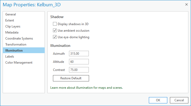
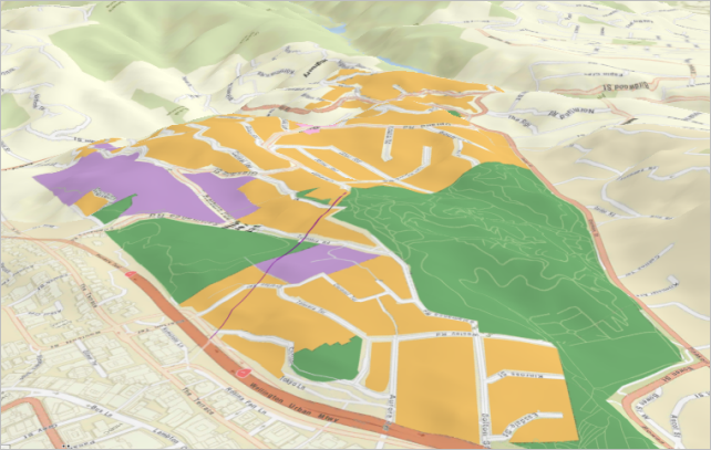
This adds shading to the terrain based on the scene's current illumination settings. However, by default, the sun altitude is 90 degrees (directly overhead), so there isn't any shading. You'll change the illumination settings, which are a property of the scene, not the elevation surface.
- In the Contents pane, right-click the scene name, Kelburn_3D, and click Properties
 .
. - On the Map Properties dialog box, click the Illumination tab.
- Under Illumination, change Altitude to 60 and press Enter.
- Click OK.
- View the scene from more perspectives.
- In the Contents pane, uncheck the WorldElevation3D/Terrain3D check box.
The scene redraws and the map layers are flat. The elevation surface layer must be turned on for its elevation values to be applied.
- Check the WorldElevation3D/Terrain3D check box to turn the layer back on.
- On the Quick Access Toolbar, click the Save button
 to save the project.
Add layers to the scene
You'll add two new layers to the scene and symbolize them. One layer represents buildings in the Kelburn suburb. This layer has an attribute you can use to extrude the buildings—that is, to draw them at their heights above the ground. The other layer represents the boundaries of Wellington suburbs. The datasets for these layers are stored in the project geodatabase.
- In the Catalog pane, on the Project tab, expand Databases. Expand convert_a_map_to_a_scene.gdb.
- Click the Buildings feature class to select it. Press the Ctrl key and click the Suburb_Boundaries feature class to select it also.
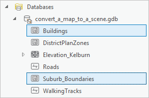
- Right-click either selected feature class and click Add To Current Map
 .
.The layers are added to the scene with default symbology. The Suburb_Boundaries layer has a solid fill color. You'll give the symbol a hollow fill and choose a different outline color.
- In the Contents pane, click the symbol for the Suburb_Boundaries layer.
The Symbology pane appears and displays polygon symbol formatting options.
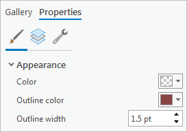
- At the top of the pane, click the Properties tab. Make sure the Symbol tab
 is selected under it.
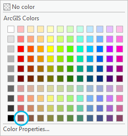
 - Under Appearance, click the Color drop-down arrow and click No Color.
- Click the Outline color drop-down arrow and click Cordovan Brown.
- Change Outline width to 1.5 pt and press Enter.
- At the bottom of the pane, click Apply.
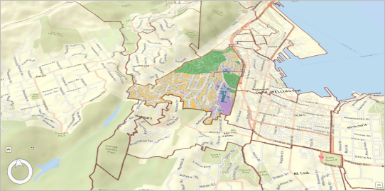
You can now see the boundary of Kelburn and the other Wellington suburbs.
- In the Contents pane, click the symbol for the Buildings layer.
You'll choose a symbol designed for buildings.
- At the top of the Symbology pane, click the Gallery tab.
- In the search box, type building and press Enter.
- In the list of symbols in the ArcGIS 2D style, click the beige Building Footprint symbol.
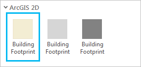
The symbol is updated in the Contents pane and in the scene. However, the buildings still lie flat on the surface. You'll extrude them using height values in the layer attribute table.
- In the Contents pane, right-click the Buildings layer and click Attribute Table
 .
.The Approximate Height field stores each building's height above ground, in meters.
Note:
The table also has a field called Base Elevation that stores the elevation value (z-value) of each feature. However, the layer is not currently using this information to position the features in 3D space. Like the other layers in the scene, the Buildings layer is using values from the WorldElevation3D/Terrain3D elevation surface.
- Close the table. In the Contents pane, make sure the Buildings layer is selected.
- On the ribbon, under Feature Layer, click the Appearance tab.
- In the Extrusion group, click Type
 and click Max Height
  .
. - Next to Type
 , click the Field drop-down arrow and click Approximate Height.
Each building is now extruded by its approximate height value in the table. The extrusion units are set to meters, which are the correct units for this layer.
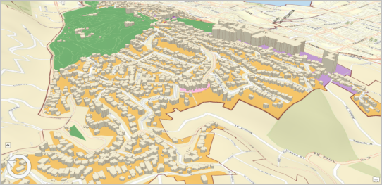
Note:
You applied the extrusion to the feature's maximum height (Max Height). To understand what that means, imagine a square building feature, defined by four vertices, lying on a slope. The feature's maximum height is the elevation of the vertex that is at the highest point on the slope. Its minimum height is the elevation of the vertex that is at the lowest point on the slope. All four vertices are extruded to the same height so that the building's roof is flat. Features extruded by their maximum height are, therefore, slightly taller than features extruded by their minimum height (unless the building lies on a flat slope). To learn more about extrusion, see Extrude features to 3D symbology.
In the Contents pane, the Buildings layer has moved from the 2D Layers category to the 3D Layers category because extrusion is a 3D property of the layer.
- On the Quick Access Toolbar, click the Save button
 .
.In the next section, you'll add another elevation surface to the scene to provide more detailed elevation values for the Kelburn suburb.
Add another elevation surface to the scene
An elevation surface is a raster or TIN dataset (or a web elevation layer created from a raster dataset) that stores elevation values for a continuous geographic area. The resolution of the surface—the amount of elevation detail it contains—may be high or low. Surfaces that cover large areas generally have lower resolution (less detail) than surfaces that cover small areas. WorldElevation3D/Terrain3D is a fairly low-resolution surface.
You can add more than one layer to an elevation surface. For example, a high-resolution layer may provide elevation values for a small area of interest, while a low-resolution layer provides elevation values for surrounding areas.
In this section, you'll add a second ground elevation layer. This layer covers the extent of the Kelburn suburb at a resolution of 1 meter. Map layers will use the elevation values of the high-resolution layer where they are available.
In most scenes, the elevation surface represents the ground: the topography of the earth's surface. However, surfaces can represent other topographies, such as cave floors or lake beds, if you have suitable datasets. To learn more about custom elevation surfaces, see Elevation surfaces.
- In the Contents pane, under Elevation Surfaces, right-click Ground and click Add Elevation Source
 .
. - In the Add Elevation Source dialog box, browse to Project > Databases > convert_a_map_to_a_scene.gdb. Click Elevation_Kelburn to select it.
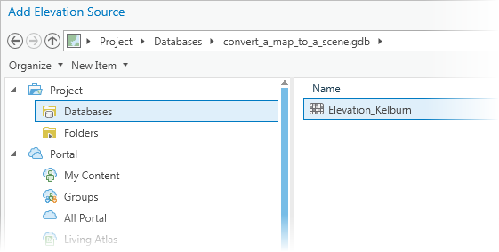
- Click OK.
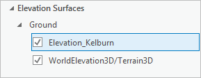
In the Contents pane, the Elevation_Kelburn layer is added above the WorldElevation3D/Terrain3D layer. Map layers use elevation values from Elevation_Kelburn wherever the map layer is coextensive with the elevation layer; where map layers extend beyond Elevation_Kelburn, they use elevation values from WorldElevation3D/Terrain3D. (In this scene, all map layers except Suburb_Boundaries are fully coextensive with Elevation_Kelburn.)
Note:
Elevation layers are used in the order in which they are listed in the Contents pane. Therefore, you should put high-resolution layers above low-resolution layers. You can drag elevation layers up and down within the Elevation Surfaces category.
- On the Quick Access Toolbar, click the Save button
 .
.
Change a layer's elevation source
A map layer is 3D if it stores z-values as part of its geometry. You can recognize a 3D layer by the Shape field of its attribute table: the values will have a Z at the end, such as PointZ, PolylineZ, or PolygonZ. By default, a 3D layer uses its own z-values to draw in 3D space.
A layer is 2D if it does not store z-values as part of its geometry. A 2D layer uses the values of the scene's elevation surface to draw in 3D space.
The Buildings layer is a 2D layer. However, it's different from the other 2D layers in the scene because it does store elevation values—not as part of its geometry, but in another field. In this section, you'll change the elevation source of the Buildings layer to this attribute field instead of using the elevation surface values.
- In the Contents pane, right-click the Buildings layer and click Attribute Table
 .
.The values in the Shape field are Polygon, not PolygonZ. This confirms the layer is a 2D layer. However, the elevation of each feature is stored in the Base Elevation field. (The layer is listed under 3D Layers in the Contents pane because its features are extruded.)
- Close the attribute table.
- In the Contents pane, right-click the Buildings layer and click Properties
 .
. - On the Layer Properties dialog box, click the Elevation tab.
The features are set to display on the ground—in other words, to use the values of the scene's ground elevation surface. This is the default setting for all 2D map layers.
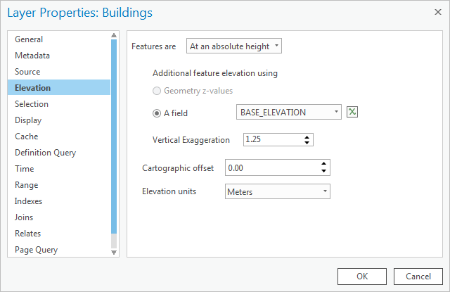
- Click the Features are drop-down arrow and click At an absolute height.
Now you can use elevation values from a source other than the scene's elevation surface—in this case, from a field.
- Under Additional feature elevation using, click the <expression> drop-down arrow and click BASE_ELEVATION.
- Set Vertical Exaggeration to 1.25.
You applied this vertical exaggeration setting to the elevation surface, so you must also apply it to the layer's new elevation source. Otherwise, the buildings will appear too low compared to the other layers in the scene.
Note:
For 3D layers, features are at an absolute height by default and feature elevation is obtained from geometry z-values.
- Make sure Elevation units is set to Meters. Click OK.
- Navigate the scene and view it from different perspectives. Zoom in for a closer look.
In several places, the buildings are partly sunken in the terrain. This can happen when multiple elevation surfaces are used in a scene. The BASE_ELEVATION values in the Buildings layer and the values in the Elevation_Kelburn surface were probably captured or processed in different ways; in any case, they don't match exactly. The values in the Buildings layer may be more accurate, but it's also important for this layer to align with the other layers in the scene. For this reason, you may want to set the elevation source for the buildings back to the ground.
- On the Quick Access Toolbar, click the Save button
 .
.
In addition to converting maps to scenes, you can import existing 3D documents from ArcScene and ArcGlobe. ArcScene documents open as local scenes and ArcGlobe documents open as global scenes. Because ArcGIS Pro and ArcScene have different 3D environments, you may need to work with the map and layer properties of an imported ArcScene document to make it display the way you want. In some cases, it's easier to create a new scene in ArcGIS Pro using the same data. Imported ArcGlobe documents generally display well in ArcGIS Pro with little or no modification.
