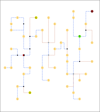
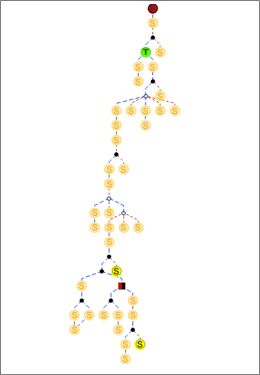
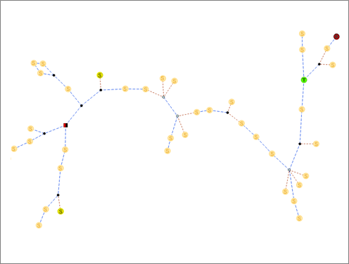
There are terms associated with network diagrams that you need to know before working with them, for example, diagram template, diagram layer, diagram map, diagram features, diagram rule, diagram layout, diagram rule and layout definitions, diagram layer definition, and so on.
Diagram template
When you generate a diagram, you choose a template on which you want your diagram to be based. The diagram template contains the definitions of the diagram rules and layouts and the definition of the diagram layer; that is, it holds the configuration properties defining the content (rule and layout definitions) and presentation (diagram layer definition) of network diagrams that will be generated.
The following three out-of-the-box diagram templates are installed by default when you create a utility network or trace network:
- Basic—This is the default template used to generate diagrams. Use this template to generate basic diagrams from the network elements currently selected in your map. A diagram feature is created for each selected network elements. Any content features or objects represented in the diagram receive a diagram feature to represent the container.
- ExpandContainers—Use this template to generate diagrams with expanded containers represented by diagram polygon containers.
- CollapseContainers—Use this template to generate diagrams with collapsed containers represented by collapsed diagram junctions and collapsed diagram edges. A single diagram line or point feature represents a container and its set of content.
As the database network owner, you can create and configure your own diagram templates and delete those installed by default if desired.
Also, while defining the subnetworks related to a tier, you can assign one or more diagram templates to that tier. In this case, diagrams representing each tier subnetwork are automatically created or updated when running the Update Subnetwork tool. These particular diagrams are called subnetwork system diagrams.
Learn about subnetwork diagram template specifics
Diagram rule and layout definitions
The diagram rule and layout definitions are set up on a diagram template. They specify how the diagrams based on that template are built, for example:
- The details of the diagram rules that are used to build the content of the diagrams
- The list of the diagram layouts that can be executed on the diagram features (whether those layouts are automatically executed at the diagram building or not)
Learn more about network diagram building
Learn more about how to manage rule and layout definitions on your templates
Diagram layer definition
The diagram layer definition is set up on a diagram template. It specifies the representation of feature layers that compose the diagram layers, that is, the representation of the layers under the network diagram layers. It behaves as the template for the display properties of specific diagrams of the network.
Learn more about network diagram layer and diagram layer definition concepts
Default diagram template
The default diagram template is the one at the top of the diagram template list that opens when you click the New drop-down arrow in the Utility Network or Trace Network tab set. 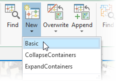
Network diagrams
Network diagrams are representations of a set of network features or network objects that participate in the utility network or trace network. 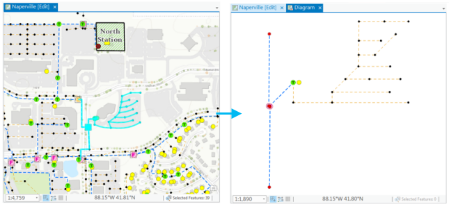
They contain diagram junctions, edges, and containers that are related to utility network or trace network elements. A network diagram is based on a diagram template. Most often, it is displayed in a diagram map as a diagram layer, and that layer renders based on a diagram layer definition. Any newly generated network diagram is temporary by default and flagged in the database to be discarded when its last diagram map view closes. You can also store a network diagram long term in the database. 
After the store operation, the temporary diagram becomes a stored diagram. It can be retrieved and reopened using the Find Diagrams pane.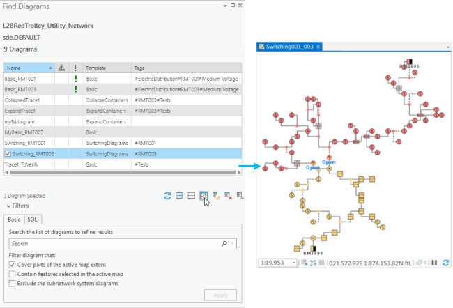
During its life cycle, a network diagram may become inconsistent regarding the network topology space. To make an inconsistent diagram return to a consistent state, you can update the diagram. Updating a diagram refers to updating its content relating to the network topology, that is, synchronizing its content with the network features and network objects used to initially generate it to reflect any changes that may have impacted those network elements in the diagram.
Diagram layer
The diagram layer is a composite layer that contains feature layers that are joins between network diagram feature classes and their associated network source classes or object tables.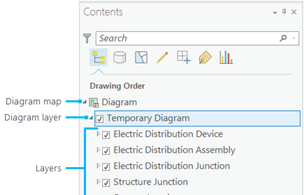
Diagram map
A diagram map is a canvas on which a network diagram displays by default. Any newly generated diagram opens in a diagram map view and results in the creation of a diagram map project item. Diagram maps can be saved with the project. As with any other map, you can have several map views related to a diagram map. However, for this particular type of map, closing the last map view of a diagram map removes the related diagram map item from the project Maps list.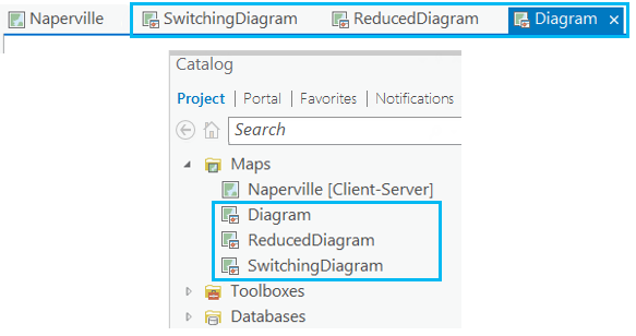
Subnetwork system diagram
A Subnetwork system diagram is a network diagram representing a subnetwork. Subnetwork system diagrams are fully managed behind the scenes—that is, created, updated, and deleted—by the Update Subnetwork tool.
Learn more about subnetwork system diagrams and their specificsDiagram graph and top graph of diagrams
The graph is the mathematical structure made up of containers and junctions, which are connected by edges.
During network diagram building, the system manages such a graph, called a diagram graph. Depending on the rules specified on the related diagram template, this diagram graph can change several times, such as after each diagram rule execution, or when diagram features have been removed, added, or aggregated in the diagram graph. At the end of the diagram building process, the final diagram graph is the network diagram itself.
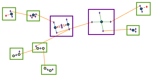
The top graph of a diagram is the diagram graph in which each container is considered as a whole junction. It is very similar to what the network diagram looks like when all its diagram containers are collapsed.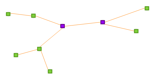
Diagram features
A network diagram contains three types of features: diagram junctions, diagram edges, and diagram containers. These diagram features represent network elements; that is, network features or network objects.
Diagram junctions
Diagram junctions are depicted as symbol point geometry and represent the following network elements:
- Point features, for example, valves, transformers, switches, and connection points
- Junction objects
- System junctions and system junction objects
- Particular edges that are reduced as junctions in the diagrams
- Polygon features that are collapsed as points in the diagram, for example, boundary structures such as pumping stations or electric substations
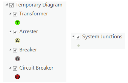
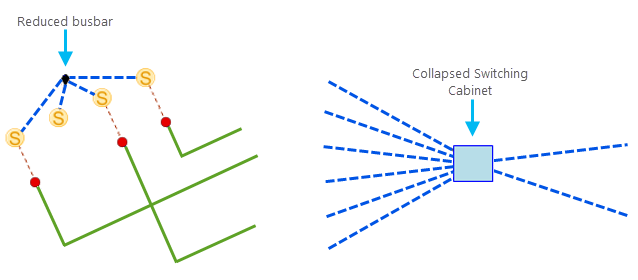
Diagram edges
Diagram edges are depicted as line geometry and represent the following network elements:
- Line features
- Edge objects
- Junction-junction connectivity associations
- Structural attachments that are not represented in the network map
- Reduction edges that aggregate several network elements in the network diagram
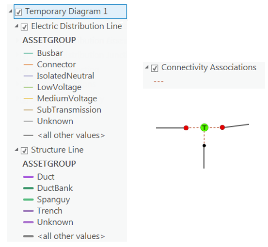
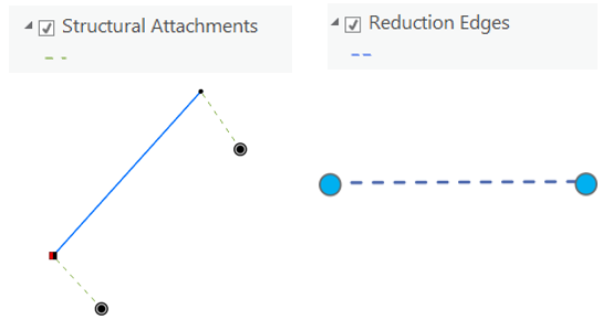
Diagram containers
Diagram containers represent network features or junction objects that contain other network features or network objects, as follows:
- Point junctions such as structure junctions, assemblies, or particular point devices
- Junction objects such as structure junction objects
- Polygon structure boundaries
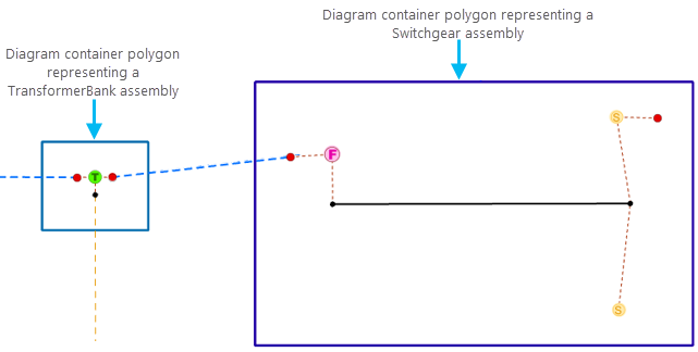
They are depicted as polygon geometry regardless of the geometry of the related network
features they represent. Diagram container geometry is computed so the container always draws around its contents.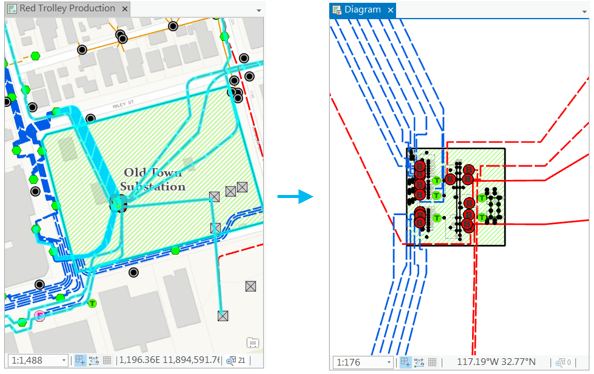
Diagram rule
A diagram rule is a specific task that executes from the initial diagram content to build the final diagram content during network diagram generation or update. Rules can be used to discard certain network elements, add extra network features or network objects (through connectivity, for example), and simplify diagram content by aggregating network elements (reduction rules and collapse rules, for example). Diagram rules are also used to configure specific flags, such as root junctions in diagrams.
Learn more about diagram building
A diagram rule is configured on the diagram template to be executed for each diagram based on that template at its generation and update. Several rules can be configured on a template. They are chained in their entry sequence order, the rule#1 running on the diagram features initially built from the set of network features or network objects used as input and the rule#N on the diagram features resulting from the execution of the rule#(N-1).
Diagram layout
A diagram layout is an algorithm that is used to clarify and normalize spacing between diagram features. 