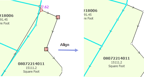
When new parcels are added to a parcel fabric, boundaries of these parcels typically do not align with existing surrounding parcels. Mismatches can occur in the following circumstances:
- New parcels are derived from parcel records with accuracies that are different from the parcel records of existing parcels.
- New parcels are from parcel records that have different bases of bearing.
- The spatial accuracy of existing parcels has been manipulated to establish topological alignment at the expense of positional accuracy.
To avoid gaps and overlaps between boundaries of adjacent parcels, use parcel alignment tools to align new parcel features with existing parcels.
You can use the following tools to align parcel features:
- Align Parcels
 —Transform parcels using links. The Align Parcels tool uses the Rubbersheet (Linear) transformation method.
 - Align Features
 —Align and reposition individual parcel lines. This tool allows you more control over the placement of boundaries when aligning parcels.
Parcel alignment
Parcel alignment is the process of spatially integrating new parcels with existing parcel boundaries so that gaps and overlaps are avoided. Parcel corners should be represented by a single point.
In general, this requires one of the following processes:
- Fitting and positioning new parcels to match existing boundaries without altering the existing boundaries
- Fitting existing boundaries to match the boundaries of positioned new parcels without altering the boundaries of new parcels
- Fitting and repositioning new and existing boundaries
Note:
Alignment of parcel features does not alter COGO dimensions on parcel lines nor the stated area on parcel polygons.When editing, a geodatabase topology or map topology can be activated in the map to maintain feature contiguity. When a parcel fabric is added to the map, the parcel fabric geodatabase topology is automatically activated in the Topology drop-down box in the Manage Edits group on the Edit tab.
When moving parcel points, topological connectivity is maintained if the parcel fabric topology is activated in the map. Parcel lines and polygons will remain coincident.
Align parcels using links
Use the Align Parcels tool  in the Alignment group on the Parcels ribbon to fit the points of selected parcels to matching points on adjacent parcels.
The Align Parcels tool transforms new parcels to surrounding boundaries or transforms surrounding boundaries to the position of new parcels. When aligning new parcels to surrounding boundaries, the new parcels are selected. When aligning surrounding boundaries to the position of new parcels, the selection is switched from the new parcels to the surrounding parcels.
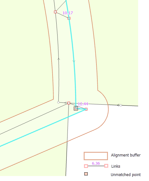
Parcels are transformed using links that are generated within a specified alignment buffer. Links can be generated between matching points of selected parcels and adjacent parcels that lie within the alignment buffer. If links are not detected between matching points, additional links can be added manually.

The Align Parcels tool transforms parcels using the Rubbersheet Linear transformation method.
Use a snap tolerance to resolve gaps and overlaps
When generating links, the position of the parcels being aligned can result in some links between matching points being undetected. These links can be added manually before aligning the parcels.
In other cases, unmatched points occur when there is no matching point found on the adjacent parcels or the selected parcels. These unmatched points are those points that should lie on adjacent parcel lines when the parcels are aligned.
Unmatched points can result in small gaps and overlaps after alignment. These gaps and overlaps can be resolved after alignment using an alignment snap tolerance. This tolerance is the distance the unmatched points lie from the aligned boundaries.
The alignment snap tolerance works as follows:
- Unmatched points of selected parcels are snapped to adjacent lines and points if the parcel features lie within the snap tolerance.
- Unmatched points of adjacent, nonselected parcels are held fixed and the following actions occur:
- Points on the selected parcels are snapped to adjacent, fixed points if the parcel points lie within the snap tolerance.
- Lines of the selected parcels are bent and snapped to adjacent, fixed points if the points and lines lie within the snap tolerance.

Align parcel features to a created path
To align and reposition individual boundary lines, use the Align Features tool  . To open the Align Features tool, select the parcels you want to align, click the Align Parcels drop-down arrow in the Alignment group on the Parcels ribbon and click Align Features
  . You can also open the tool from the Tools gallery on the Parcels ribbon and from the Modify Features pane.
Use the Align Features tool to trace a path over the boundaries you want to hold as fixed in the alignment. Surrounding boundaries that lie within the Alignment Tolerance in the Align Features pane move to the traced path when you click Align. In this way, you can keep the boundaries of new parcels in fixed positions and move surrounding boundaries to the new boundaries, even if their line shapes do not match.
You can use the Align Features tool to align parcel features in the following ways:
- Trace a path over the boundaries you want to hold as fixed. Adjacent boundaries that lie within the Alignment tolerance in the Align Features pane move to the traced boundaries.
This allows you to hold the boundaries of new parcels as fixed during the alignment process.
- Use editing tools to draw a path for a new, shared boundary location. Adjacent boundaries that lie within the Alignment tolerance in the Align Features pane move to the location of the drawn path.
This allows you to define a new boundary location and shape for adjacent boundaries to move to in the alignment process.
Tip:
When drawing a new boundary path for aligning parcel features, the drawn path can include circular arcs. Existing, densified boundary lines that represent curves can be updated to the new, correct circular arc geometry.