Reshape Diagram Edges is a refinement layout algorithm that processes edges. It applies to any type of diagram.
This layout is used to process simple operations on vertices along edges in network diagrams. It allows you to do the following:
- Remove all vertices along diagram edges.
- Reduce some vertices along diagram edges.
- Square diagram edges with the addition of vertices on edges.
- Separate diagram edges that overlap.
- Detect diagram edges that cross each other at right angles and reshape their geometries to display a circular arc at the crossing locations.
Apply the Reshape Diagram Edges layout on an active diagram map view
When applying this layout on a network diagram, the following prerequisites must be met:
- Since this operation is transactional, edits must be saved before it is run.
- The input network diagram layer to which the layout applies must be from either a utility network or trace network in a file geodatabase, or a network diagram service. When working with a utility network or a trace network in an enterprise geodatabase, the input network diagram layer must be from a service
To apply the Reshape Diagram Edges layout on an active diagram map view, do one of the following choices:
- On the Network Diagram tab, click the drop-down arrow on the Diagram Layouts button in the Layout group, and click the Reshape Diagram Edges layout item in the gallery
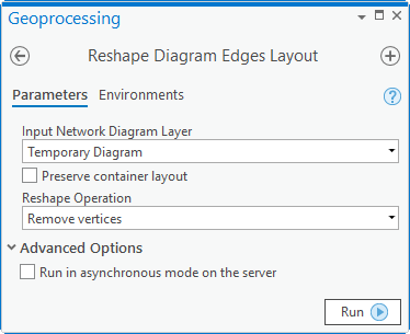
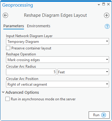
- Load the Reshape Diagram Edges Layout tool in the Geoprocessing pane.
Then, adjust the Reshape Diagram Edges layout parameters and click Run.
Note:
To apply the layout on a subset of features in the network diagram, use one of the Select Features tools (for example, Select By Rectangle, Select By Polygon, and so on) and select the diagram features before running.
Configure the Reshape Diagram Edges layout on a diagram template
To configure this layout on your diagram template, use the Add Reshape Diagram Edges Layout tool.
Reshape Diagram Edges layout parameters
The sections below clarify the main Reshape Diagram Edges diagram layout parameters.
Preserve container layout
Most of the layout algorithms work with the Preserve container layout option. This option allows controlling the algorithm execution so it executes either on the top graph of the diagram—Preserve container layout checked, or on both content and noncontent features in the diagram—Preserve container layout unchecked.
Reshape operation = Square edges
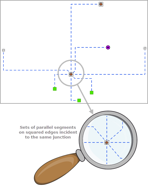
When running the Reshape Diagram Edges layout with Reshape operation set to Square edges, vertices are placed along diagram edges so they display with right angles.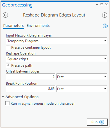
The images below show a diagram sample before and after applying the Reshape Diagram Edges layout with the Square edges operation: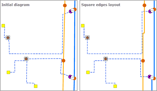
Preserve path
This parameter specifies whether vertices along the edges that are going to be squared will be preserved. When this option is enabled, the direction of any edge will be considered and vertices along that edge will be preserved, from the first vertex to the last.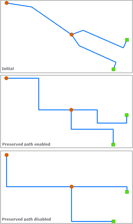
Offset Between Edges and Break Point Position
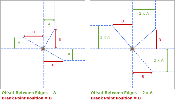
Offset Between Edges is used to set the spacing that will separate parallel segments of squared edges incident to the same junction; that is, the A green spacing in the image below.
Break Point Position allows to set the maximum distance between each junction to the first or last break point along edges incident to that junction when those edges are squared; that is the B burgundy distance in the image below:
Reshape operation = Remove vertices
When running the Reshape Diagram Edges layout with Reshape operation set to Remove vertices, all vertices along any edges in the diagram are removed.
The images below show a diagram sample before and after applying the Reshape Diagram Edges layout with the Remove vertices operation: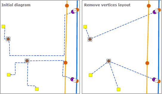
Reshape operation = Separate overlapping edges
When running the Reshape Diagram Edges layout with Reshape operation set to Separate overlapping edges, all edges that connect the same origin and extremity junctions are separated where they were overlapping.
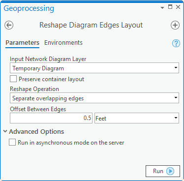
Offset Between Edges
This parameter specifies the absolute spacing that separates two edges that were overlapping after the layout completes: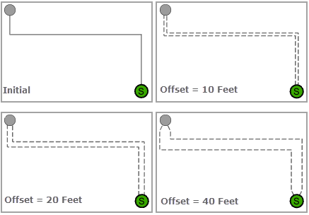
Reshape operation = Reduce vertices by angle
When running the Reshape Diagram Edges layout with Reshape operation set to Reduce vertices by angle, some or all vertices displayed along diagram edges are reduced according to the angle that separates the segments incident to those vertices.
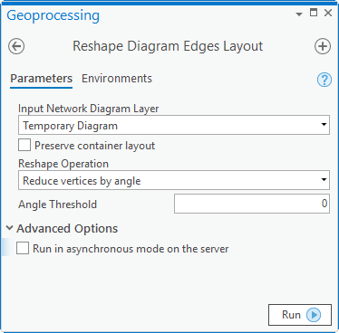
The images below show a diagram sample before and after applying the Reshape Diagram Edges layout with the Reduce vertices by angle operation: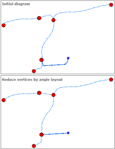
Angle Threshold
This parameter specifies the angle formed by the incident segments over which the vertex related to these segments is reduced. The wider the angle, the fewer vertices are reduced.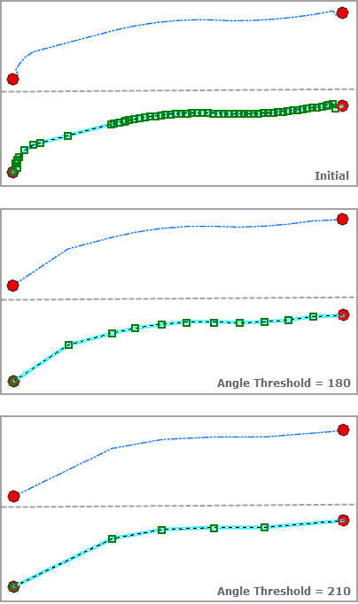
Reshape operation = Mark crossing edges
When running the Reshape Diagram Edges layout with Reshape operation set to Mark crossing edges, horizontal and vertical diagram edges that cross each other at a right angle in the diagram will be marked and the geometry of one of the crossing edges will be reshaped to display a circular arc at this location.
The images below show a diagram sample before and after applying the Reshape Diagram Edges layout with the Separate overlapping edges operation: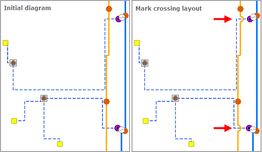
Circular Arc Radius
This parameters is used to set the radius of the circular arc that is added at the crossing edge locations: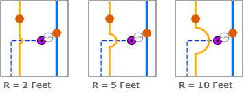
Circular Arc Position
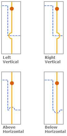
This parameter specifies the segment on which the circular arcs will be placed.
- Left of vertical segment—A circular arc will be placed to the left of the vertical segment.
- Right of vertical segment—A circular arc will be placed to the right of the vertical segment.
- Above horizontal segment—A circular arc will be placed above the horizontal segment.
- Below horizontal segment—A circular arc will be placed below the horizontal segment.
