Available with Pipeline Referencing license.
Characteristics of a route can be represented as a line event with start and end measure information along the route.
Use the Add Multiple Line Events tool  to add multiple line events at the same time.
The example in the following workflow demonstrates adding multiple line events.
The following diagram details the routes and their attributes.
The following table details attributes for the routes (R1, R2, and R3) that belong to LineA. Events will be added between R1 and R3.
| Route ID | From Date | To Date |
|---|---|---|
R1 | 1/1/2000 | <Null> |
R2 | 1/1/2000 | <Null> |
R3 | 1/1/2000 | <Null> |
- Open the map in ArcGIS Pro and zoom in to the location where you want to add the line events.
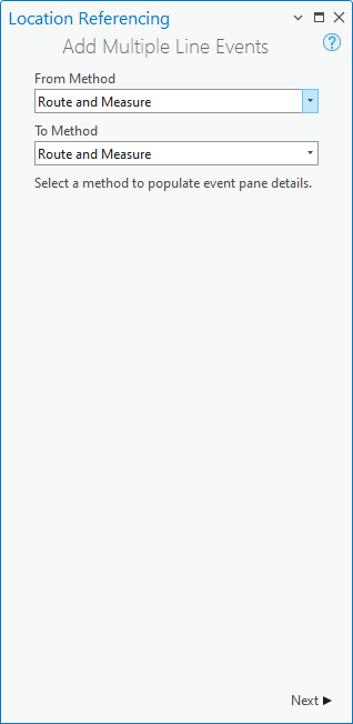
- Click the Location Referencing tab, and in the Events group, click the Add drop-down menu and choose Multiple Line Events
 .
.The Add Multiple Line Events pane appears.

The Route and Measure method locates the event's measures based on measure values from the selected route.
- Click Next.
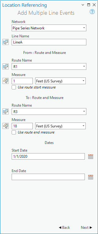
The Route and Measure and Dates fields appear in the Add Multiple Line Events pane.

- Click the Network drop-down arrow and choose the LRS Network of the route to which you want to add line events.
The network serves as the source linear referencing method (LRM) to define the input measures for the event.
The network is an LRS Network published as a layer in the feature service.
- If the selected network is a line network, click Choose line from map
 and choose a line from the map to populate the Line Name text box.
Alternatively, provide the line name in the Line Name text box.
- In the From: Route and Measure section, click the Choose route from map button
 and select the from route on the map.
Alternatively, provide the route name in the Route Name text box.
Note:
After clicking the Choose route from map button
 or the Choose measure from map button
  , you can
hover over the routes to see the route and measure at the location of the pointer.
, you can
hover over the routes to see the route and measure at the location of the pointer.You can set map scale options for display of route and measure information on the Options dialog box, on the Location Referencing tab.
Note:
If a message regarding acquiring locks or reconciling appears, conflict prevention is enabled.
- In the From: Route and Measure section, specify the start measure for the new line events along the route by doing one of the following to populate the Measure text box.
- Click the Choose measure from map button
 and choose the start measure value along the route on the map.
 - Check the Use route start measure check box.
- Provide the start measure value in the Measure text box.
A green point appears at the selected location on the map.
- Click the Choose measure from map button
- In the To: Route and Measure section, click the Choose route from map button
 and select the to route on the map.
Alternatively, provide the route name in the Route Name text box.
- In the To: Route and Measure section, specify the end measure for the new line events along the route by doing one of the following to populate the Measure text box.
- Click the Choose measure from map button
 and choose the start measure value along the route on the map.
 - Check the Use route end measure check box.
- Provide the end measure value in the Measure text box.
A red point appears at the selected location on the map.
The new events will be created between the green and red dots.
- Click the Choose measure from map button
- Specify the start date of the line events by doing one of the following:
- Provide the start date in the Start Date text box.
- Double-click in the Start Date text box to use today's date.
The start date default value is today's date, but you can choose a different date using the date picker.
- Optionally, specify the end date of the event by doing one of the following:
- Click Calendar
 and choose the end date.
 - Provide the end date in the End Date text box.
- Double-click in the End Date text box to use today's date.
If no end date is provided, the event remains valid now and into the future.
- Click Calendar
- Click Next.
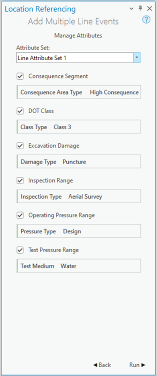
The Manage Attributes table appears with the default attribute set.
The Attribute Set list includes other attribute sets if configured.
- Optionally, choose an attribute set from the Attribute Set drop-down list.
You can configure attribute sets for yourself and for others in the same feature service.
- Provide attribute value information for the events in the attribute set.

Note:
Coded values, range domains, subtypes, contingent values, and attribute rules are supported when configured for a field in an Attribute Value table.
- Click Run.
A confirmation message appears once the line events are added and appear on the map.
The following tables detail the line events by event layer:
Consequence Segment
| Event | From Route ID | To Route ID | From Date | To Date | From Measure | To Measure | Location Error | Consequence Area Type |
|---|---|---|---|---|---|---|---|---|
Event1 | R1 | R3 | 1/1/2000 | <Null> | 1 | 18 | No Error | High Consequence |
DOT Class
| Event | From Route ID | To Route ID | From Date | To Date | From Measure | To Measure | Location Error | Class Type |
|---|---|---|---|---|---|---|---|---|
Event1 | R1 | R3 | 1/1/2000 | <Null> | 1 | 18 | No Error | Class 3 |
Excavation Damage
| Event | From Route ID | To Route ID | From Date | To Date | From Measure | To Measure | Location Error | Damage Type |
|---|---|---|---|---|---|---|---|---|
Event1 | R1 | R3 | 1/1/2000 | <Null> | 1 | 18 | No Error | Puncture |
Inspection Range
| Event | From Route ID | To Route ID | From Date | To Date | From Measure | To Measure | Location Error | Inspection Type |
|---|---|---|---|---|---|---|---|---|
Event1 | R1 | R3 | 1/1/2000 | <Null> | 1 | 18 | No Error | Aerial Survey |
Operating Pressure Range
| Event | From Route ID | To Route ID | From Date | To Date | From Measure | To Measure | Location Error | Pressure Type |
|---|---|---|---|---|---|---|---|---|
Event1 | R1 | R3 | 1/1/2000 | <Null> | 1 | 18 | No Error | Design |
Test Pressure Range
| Event | From Route ID | To Route ID | From Date | To Date | From Measure | To Measure | Location Error | Test Medium |
|---|---|---|---|---|---|---|---|---|
Event1 | R1 | R3 | 1/1/2000 | <Null> | 1 | 18 | No Error | Water |
The following image shows the route and the associated line events that begin at 1 on R1 and end at 18 on R3 after the edit.